

Capacitor Types Explained: How to Choose the Right Type
September 3, 2026
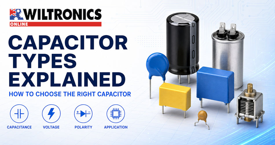
Capacitor Types Explained: How to Choose the Right Type
Capacitors smooth power supplies, remove noise, couple signals, create time delays, tune radios, start motors and store energy. Yet two parts with the same capacitance can behave very differently. A reliable choice must also account for voltage, polarity, dielectric, tolerance, temperature, equivalent series resistance (ESR), ripple current, safety class, size and intended duty.
This guide explains the main capacitor types, common markings and a practical selection process for electronics projects, servicing and education.
Safety first: Capacitors can retain hazardous energy after equipment has been switched off or disconnected. Mains-connected equipment, motor circuits and high-voltage apparatus require appropriate training, test equipment and isolation procedures. Never assume a capacitor is discharged and never short its terminals with a screwdriver. A suitably qualified or licensed person should service equipment where Australian electrical-safety requirements apply.
Quick capacitor selector
| Capacitor type | Common uses | Polarised? | Important checks | Explore |
|---|---|---|---|---|
| Ceramic | Decoupling, RF, filtering, timing | No | Dielectric, tolerance, effective capacitance under bias | Ceramic capacitors |
| Aluminium electrolytic | Power-supply smoothing, bulk energy storage | Usually | Polarity, voltage, temperature, ESR and ripple current | Electrolytic capacitors |
| Film, polyester and MKT | Signal coupling, timing, filtering and general AC/DC circuits | No | Dielectric, tolerance, voltage and pulse duty | Poly, MKT, monolithic and suppression capacitors |
| X2 or Y2 safety capacitor | Mains interference suppression | No | Exact safety class, approvals and rated AC voltage | Class X2 mains-suppression capacitors |
| Tantalum | Compact power filtering and decoupling | Yes | Polarity, surge conditions and voltage derating | Tantalum capacitors |
| Supercapacitor | Memory backup, energy hold-up and low-power storage | Yes | Low voltage limit, leakage, balancing and charge control | 1F 5.5V supercapacitor |
| Motor run | Continuous operation with a single-phase motor | No | Run duty, capacitance, AC voltage, terminals and mounting | Motor run and start capacitors |
| Motor start | Short-duration starting torque | No | Start duty, capacitance range, voltage and duty cycle | Motor run and start capacitors |
| Trimmer or tuning | Adjustable RF and oscillator circuits | No | Capacitance range, adjustment style and circuit voltage | Trimmer and tuning capacitors |
Find the right capacitor in 60 seconds
- Identify the function. Is it filtering a DC rail, coupling a signal, suppressing mains interference, tuning a circuit or operating a motor?
- Match capacitance and tolerance. Use the equipment specification, schematic or verified original part.
- Confirm voltage and supply type. Distinguish DC, ordinary AC, mains-safety and motor ratings.
- Check polarity and construction. Match the required electrolytic, ceramic, film, tantalum or specialist type.
- Verify operating stress. Check ESR, ripple current, temperature, duty and expected life where relevant.
- Confirm the fit. Compare dimensions, lead spacing, terminals and mounting before ordering.
If any mains-safety class, motor duty or original marking remains uncertain, stop and obtain the correct service information.
What does a capacitor do?
A capacitor stores separated electric charge in an electric field. Its capacitance describes how much charge it stores for a given voltage:
Q = C × V
where Q is charge in coulombs, C is capacitance in farads and V is voltage. In changing circuits, frequency-dependent behaviour lets capacitors bypass noise, couple AC signals while blocking DC, and form filters, timers and resonant circuits. Real components also have resistance, inductance, leakage and operating limits determined by their construction.
Understanding pF, nF and µF
The farad is a large unit, so most electronic capacitors use smaller units:
- 1 microfarad (µF) = 1,000 nanofarads (nF)
- 1 nanofarad (nF) = 1,000 picofarads (pF)
- 1 microfarad (µF) = 1,000,000 picofarads (pF)
Useful conversions include:
| Marking | Equivalent values |
|---|---|
| 100pF | 0.1nF = 0.0001µF |
| 1nF | 1,000pF = 0.001µF |
| 10nF | 10,000pF = 0.01µF |
| 100nF | 100,000pF = 0.1µF |
| 1µF | 1,000nF = 1,000,000pF |
Do not confuse a decimal point or unit during replacement. A 0.1µF capacitor has 100 times the capacitance of a 0.001µF capacitor.
Seven questions to ask before choosing a capacitor
1. What capacitance does the circuit require?
Capacitance affects timing, filtering, smoothing and stored energy. Match the specified value and tolerance. A larger value can increase inrush current, stress rectifiers or alter circuit behaviour, so treat any change as a design decision—not an automatic upgrade.
2. What voltage will appear across it?
The rating must exceed the maximum applied voltage, including relevant transients. An equal or higher voltage rating often works in low-voltage circuits when every other specification and the physical fit also match. Voltage alone does not establish compatibility: a high-voltage generic part cannot replace a safety capacitor, and a DC rating does not qualify it for mains, motor or pulse duty.
3. Does polarity matter?
Ceramic and most film capacitors are non-polarised. Aluminium electrolytic, tantalum and many supercapacitors are polarised; reverse voltage can cause leakage, heating, venting or catastrophic failure. A stripe often identifies an aluminium electrolytic’s negative terminal, but confirm the component marking and datasheet.
4. Is the circuit DC, AC or connected to mains?
A low-voltage DC rail, mains input and motor winding impose different stresses. Use the specified safety class for mains suppression, match start or run duty for motors, and check ESR, ripple and temperature in switching power circuits.
5. Which construction or dielectric suits the job?
Dielectric choice affects density, stability, loss, frequency behaviour and size. Ceramic, electrolytic, film and tantalum parts are not interchangeable merely because their nominal capacitance and voltage match.
6. What current and temperature stresses will it face?
ESR converts ripple current into heat, while excess temperature accelerates ageing. Check the original documentation for ESR class, ripple capability, temperature and expected life.
7. Will it physically fit and connect correctly?
Confirm case dimensions, lead spacing, axial or radial format, terminals, mounting and clearance. Correct electrical specifications are not enough if the part cannot mount securely.
Ceramic capacitors: small, fast and widely used
Ceramic capacitors are non-polarised and commonly used for high-frequency bypassing, decoupling, RF circuits, filters and oscillators. Their low inductance and small size make them useful close to integrated-circuit supply pins.
Not all ceramic dielectrics behave alike. Class 1 types such as C0G/NP0 offer high stability, low loss and minimal capacitance change with voltage, making them suitable for precision timing and resonant circuits. High-capacitance Class 2 dielectrics such as X7R or X5R offer more capacitance in less space, but their effective capacitance can decrease as DC bias rises. Temperature, frequency and ageing can also influence measured capacitance.
This matters when a compact multilayer ceramic capacitor must provide bulk decoupling. The value printed on the part may be its nominal value under specified test conditions, not necessarily the capacitance available at the circuit’s operating voltage. Manufacturer selection data should guide critical designs. Murata’s ceramic-capacitor selection guide and DC-bias explanation illustrate these effects.
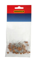
For prototyping and teaching, the 60-piece ceramic capacitor pack provides values from 10pF to 0.1µF for filters, timing experiments and decoupling.
Aluminium electrolytic capacitors: high capacitance for power circuits
Aluminium electrolytics provide relatively high capacitance in a compact, economical package. Common applications include rectifier smoothing, DC-bus filtering, audio coupling and local energy storage.
Most are polarised. They also have higher leakage and less favourable high-frequency behaviour than many ceramic or film capacitors. Their liquid or polymer electrolyte and internal construction make temperature, ripple current and useful life important design considerations.
When replacing a power-supply electrolytic, check:
- capacitance and tolerance
- working voltage
- polarity
- radial or axial lead format
- case dimensions and lead spacing
- temperature rating
- ESR or impedance series
- ripple-current rating
- specified endurance or useful life
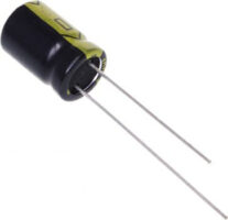
A general-purpose electrolytic may not survive in the hot, high-ripple output stage of a switchmode power supply. A low-impedance ESR electrolytic better suits applications that specify that performance class. TDK’s industrial guidance similarly highlights ESR, thermal behaviour and ripple-current capability as key power-capacitor characteristics.
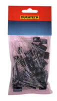
Wiltronics also stocks a 10000µF 40V radial electrolytic, plus the 55-piece RB electrolytic pack and RT electrolytic value pack for laboratories and workshops.
Selecting parts for a power supply? Start with the Wiltronics electrolytic capacitor range, then filter by capacitance, voltage, format and required ESR performance.
Film, polyester and MKT capacitors
Film capacitors use a plastic-film dielectric. They are generally non-polarised and offer good insulation resistance, low loss and dependable AC performance. Polyester film, often marked MKT, provides a practical balance of size, price and performance for signal coupling, timing, filters and general electronics.
Compared with aluminium electrolytics, film capacitors are often more stable and better suited to repetitive AC or pulse operation, but they become physically larger at high capacitance values. Polypropylene film types can offer lower loss and improved pulse or AC performance in applications designed for them.
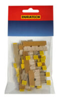
The Wiltronics range includes polyester, MKT, monolithic, X2 and Y2 capacitors and a 50-piece MKT polyester capacitor pack for prototyping and classroom investigations.
X2 and Y2 safety capacitors: class is part of the specification
Safety capacitors suppress electromagnetic interference in circuits connected to the mains. Their construction and certification address defined impulse and failure conditions.
- Class X capacitors connect across active and neutral. An X2 capacitor is common in domestic and commercial equipment connected to typical low-voltage mains supplies.
- Class Y capacitors connect between a live conductor and protective earth or another accessible reference, where failure could create an electric-shock hazard.
Never replace an X or Y safety capacitor with an ordinary ceramic, film or high-voltage DC capacitor. Match the capacitance, safety class, rated AC voltage, approval requirements, lead spacing and application. A different safety subclass is not an automatic substitute.
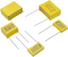
Wiltronics stocks both Class X2 mains-suppression capacitors and Class Y2 mains-suppression capacitors. Choose only after confirming the circuit position and required class. A qualified person should service mains-powered equipment under appropriate electrical-safety procedures.
Tantalum capacitors: compact but polarity-sensitive
Tantalum capacitors deliver relatively high capacitance in a small package, with low leakage and stable characteristics over time and temperature. Designers use them for filtering and decoupling where size matters.
They require careful treatment. Tantalum capacitors are polarised and can respond badly to reverse voltage, excessive surge current or inadequate voltage derating. Replacing one with a superficially similar part without checking series and surge requirements can create a reliability problem.
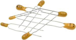
The Wiltronics tantalum capacitor range covers multiple values. Always verify polarity before applying power.
Supercapacitors: energy storage at low voltage
Supercapacitors offer fractions or whole farads for memory retention, ride-through power, energy harvesting or short current bursts. They are not drop-in replacements for filter capacitors or batteries: low cell-voltage limits, leakage and different charge behaviour may require current limiting, control and series-cell balancing.
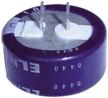
The 1F 5.5V PCB-mount supercapacitor suits compatible low-voltage backup and hold-up projects when the circuit respects its voltage and current limits.
Motor start versus motor run capacitors
Single-phase induction motors often use capacitors to create the phase shift needed for starting torque or efficient running. Start and run capacitors perform different jobs and are not interchangeable.
Motor start capacitors
Motor start capacitors provide high capacitance for a short period while the motor accelerates. A switch or relay should remove them from the circuit after startup. Their intermittent-duty construction does not suit continuous energisation.
Motor run capacitors
Motor run capacitors remain energised while the motor operates. Metallised polypropylene film construction is common because it supports continuous AC duty and offers self-healing behaviour in appropriate designs.
For either type, match:
- the motor’s specified start or run function
- capacitance or capacitance range
- rated AC voltage
- duty and safety category
- frequency where specified
- terminal arrangement
- dimensions and mounting method
Do not diagnose a motor only by replacing its capacitor. Bearings, windings, switches, relays, supply voltage and mechanical load can produce similar symptoms. TDK’s motor start and motor run overview reinforces the application-specific nature of these components.
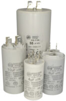
Once the specification is known, compare Wiltronics 450VAC motor run capacitors and intermittent-duty motor start capacitors. The broader motor capacitor range includes alternative mounting formats.
Trimmer and tuning capacitors
Trimmer capacitors provide a small adjustable capacitance for calibration, oscillator alignment, impedance matching and RF tuning. Tuning capacitors offer a wider user-adjustable range in equipment such as radio receivers.
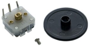
Select them by capacitance range, working voltage, mounting, adjustment method and RF performance. Avoid forcing a trimmer beyond its mechanical travel. The 60–160pF tuning capacitor suits compatible crystal-set and transistor-radio projects; Wiltronics also stocks a broader trimmer and tuning capacitor range.
How to read common capacitor markings
Large electrolytics often print capacitance and voltage directly, such as 470µF 25V. Small ceramic and film parts may use three digits: two significant figures followed by the number of zeros in picofarads.
| Code | Calculation | Value |
|---|---|---|
| 101 | 10 × 10¹pF | 100pF |
| 102 | 10 × 10²pF | 1,000pF = 1nF |
| 103 | 10 × 10³pF | 10nF = 0.01µF |
| 104 | 10 × 10⁴pF | 100nF = 0.1µF |
| 473 | 47 × 10³pF | 47nF = 0.047µF |
Tolerance letters commonly include J for ±5%, K for ±10% and M for ±20%, although the applicable marking system and datasheet should always take priority. Other markings may identify dielectric, temperature range, series, date or safety approvals.
A faded label creates uncertainty. Do not infer a critical replacement solely from colour, case size or a partly legible code; consult the schematic, parts list, manufacturer or an identical verified unit.
ESR, ripple current and temperature: the hidden replacement specifications
ESR represents resistive loss inside a capacitor. Ripple current produces heat approximately according to P = I²R, so increased current, ESR or poor cooling raises internal temperature. A degraded capacitor may therefore measure near its marked capacitance but still fail under load.
Nearby hot components and restricted airflow also shorten life. Check cooling, load, voltage and surrounding parts before fitting a replacement with the required ESR, ripple rating, temperature rating and endurance.
Capacitors in parallel and series
Parallel capacitances add directly: Ctotal = C1 + C2 + … The voltage must remain within the lowest-rated member’s limit.
Series capacitances follow 1/Ctotal = 1/C1 + 1/C2 + … Two identical parts in series give half the capacitance, but leakage differences can produce unequal voltage sharing. High-voltage strings may require engineered balancing networks; never improvise a substitute bank in mains or high-energy equipment.
How to test a capacitor safely
- Inspect it: Look for bulging, leakage, cracking, corrosion, heat damage or loose terminals. A normal appearance does not prove good condition.
- Measure capacitance: A suitable multimeter or LCR meter can identify open, shorted or out-of-tolerance parts. Out-of-circuit readings avoid interference from parallel components.
- Check ESR where relevant: An ESR meter can reveal degraded electrolytics that retain much of their capacitance. Compare results with suitable manufacturer data; no universal ESR limit fits every part.
- Control stored energy: Isolate the equipment, follow an approved discharge procedure and verify voltage before contact. Recheck circuits subject to dielectric absorption or another charging source. Leave mains and high-energy equipment to a trained technician.
Capacitor replacement checklist
| Check | What to confirm | Why it matters |
|---|---|---|
| Circuit function | Filtering, timing, coupling, safety suppression, start or run | Determines suitable capacitor family and duty |
| Capacitance | Value and tolerance | Affects timing, ripple, tuning and motor performance |
| Voltage | DC or AC rating plus transient requirements | Prevents dielectric overstress |
| Polarity | Orientation and allowable reverse voltage | Incorrect connection can cause failure or injury |
| Construction | Ceramic, electrolytic, film, tantalum or other specified type | Controls stability, loss, frequency response and life |
| Safety class | X2, Y2 or other specified approval | Ordinary parts cannot replace certified safety capacitors |
| ESR and ripple | Series performance and current capability | Controls heating and power-supply performance |
| Temperature and life | Rated temperature and endurance | Influences reliability in warm equipment |
| Duty | Continuous, intermittent, pulse or motor service | Prevents misuse outside the part’s design |
| Mechanical fit | Size, lead spacing, terminals and mount | Ensures secure, insulated installation |
Common capacitor-selection mistakes
| Mistake | Better approach |
|---|---|
| Matching capacitance alone | Also verify voltage, polarity, construction, ESR, ripple and duty. |
| Assuming higher voltage fixes everything | Remember that voltage cannot substitute for safety class, AC duty or dielectric performance. |
| Treating every 0.1µF part as equivalent | Select C0G, X7R, polyester film or X2 according to the circuit function. |
| Reversing a polarised part | Cross-check the PCB, schematic and component markings. |
| Interchanging motor start and run types | Match the specified role, capacitance, AC voltage and duty cycle. |
| Replacing the symptom only | Investigate heat, cooling, ripple, overvoltage, switches and surrounding components. |
| Buying by appearance | Use electrical, safety and mechanical specifications—not case shape or colour. |
Building a useful capacitor assortment for education and prototyping
A small assortment helps students connect theory with measurement. Rather than collecting random parts, include complementary families:
- low-value ceramic capacitors for high-frequency filtering and timing
- polyester or MKT capacitors for non-polarised signal and RC experiments
- aluminium electrolytics for power-supply smoothing and charge/discharge investigations
- one supercapacitor for low-voltage energy-storage comparisons
- appropriate resistors, breadboards, leads and a capacitance-capable multimeter
The ceramic capacitor pack, MKT polyester pack and RB electrolytic pack cover distinct ranges and construction types.
Useful investigations include plotting an RC charging curve, comparing smoothing ripple at different capacitances, building low-pass and high-pass filters, decoding marked values, and testing the effect of series and parallel combinations. Keep classroom work at safe extra-low voltage and use current limiting where appropriate.
Frequently asked questions
Can I replace a capacitor with a higher voltage rating?
Often yes in a low-voltage electronic circuit, if capacitance, polarity, construction, ESR, ripple, temperature, physical fit and other requirements also match. A higher voltage rating does not replace the need for the correct X/Y safety class, motor duty or AC rating.
Can I use a slightly higher capacitance?
Only when the circuit design allows it. Increasing capacitance can alter timing, filter response, inrush current, feedback stability or motor current. Use the specified value and tolerance unless reliable service information supports a change.
What is the difference between ceramic and electrolytic capacitors?
Ceramic capacitors are generally non-polarised, small and effective at high frequencies. Aluminium electrolytics are usually polarised and provide much higher capacitance economically, making them common for bulk power filtering. Their different behaviour means one is not a universal substitute for the other.
What does 104 mean on a capacitor?
It means 10 followed by four zeros in picofarads: 100,000pF, which equals 100nF or 0.1µF.
What is a low-ESR capacitor?
It has relatively low equivalent series resistance for its design and operating conditions. Low ESR reduces internal heating and voltage loss when ripple current flows, which is important in many switchmode power supplies. Match the specified series and ripple capability rather than relying only on the words “low ESR”.
Can I replace an X2 capacitor with a normal film capacitor?
No. Use a properly approved capacitor of the required safety class and AC rating. Safety classification describes controlled behaviour in a mains application; an ordinary film capacitor’s voltage rating does not provide the same qualification.
Are motor start and motor run capacitors interchangeable?
No. Start capacitors work intermittently during acceleration, while run capacitors operate continuously. Match the motor manufacturer’s capacitance, voltage, duty, terminals and mounting specification.
Why did a new capacitor fail again?
Possible causes include the wrong replacement type, reversed polarity, excessive ripple, high temperature, overvoltage, a failed motor switch, poor ventilation or another defective circuit component. Diagnose the operating conditions before fitting another part.
Choose capacitors by function, not appearance
The best capacitor selection starts with the circuit’s job. Establish the required capacitance and voltage, then confirm polarity, construction, ESR, ripple current, temperature, safety class, duty and physical fit. That process prevents the most common replacement mistakes and makes component purchasing far more reliable.
Explore the complete Wiltronics capacitor range for ceramic, electrolytic, film, suppression, tantalum, supercapacitor, motor and tuning applications.
If a replacement involves mains power, motors or stored high voltage, identify the original specification and have an appropriately qualified person complete the diagnosis and installation.
© Electrotech Brands Pty Ltd 2026
Write a Comment
You must be logged in to post a comment.