Voltmeter vs Ammeter: Defining Their Differences
April 8, 2022

Voltmeter vs ammeter — what is the difference?
You can measure electricity in two ways; one is through current (I), and the other is through voltage (V). These two are quantities in electricity: voltage is the cause, and current is the effect.
They may be in a direct relationship, but they measure different things. This is where the ammeter (A) and voltmeter (V) come into play.
An ammeter measures current, whereas a voltmeter measures voltage. Today, these are usually found within the same physical device, such as a multimeter.
Both of these devices are used in electric circuits. But the major difference will be explained further here. Keep reading!
Ammeters Explained
An ammeter measures the electric current in a circuit in milliamperes or micro-amperes (μA). It is placed in series with the measuring circuit so the whole current passes through it.
The name is derived from the name for the SI unit (Ω) for electric current, amperes (A).
Ammeters are built by placing a galvanometer in parallel with a “shunt” resistor, Rs. The shunt is a small resistor that deflects the current away from the galvanometer.
Because of that, most of the current goes through the shunt resistor. And to measure a device’s current, you must connect it in series to that tool. You must not connect them to a voltage source as ammeters work under a minimal burden.
The resistance of the ammeter is very small, with a value of 0, unlike the voltmeter. The low value does not obstruct the current flow, and thus ammeters measure the true value.
Voltmeters Explained
A voltmeter comes in handy for measuring the voltage or emf across two points in an electric circuit. It is designed to measure the difference between two points in an electric circuit.
To measure a potential difference across a component, you must place it in parallel. This is necessary because objects in parallel experience the same potential difference.
For instance, a voltmeter is placed in parallel with a resistor to measure the voltage across it.
The connection polarity of the voltmeter is the same as that of the ammeter. The positive terminal connects to the positive polarity of the supply. Meanwhile, the negative potential connects to the negative polarity.
But the resistance across the voltmeter is very large, unlike the ammeter. The value of resistance in an ideal voltmeter is approximately equal to infinity.
This resistance does not allow the current to flow through the voltmeter. Thus, the exact value of the voltage across the measuring point is measured.
Voltmeter vs Ammeter: Works as Galvanometer
At the heart of most analogue meters is a galvanometer. It is an instrument that measures current flow using the movement or deflection of a needle.
The needle deflection is caused by a magnetic force acting on a current-carrying wire. The working principle of the ammeter and voltmeter are the same as the galvanometer.
A galvanometer uses a coil that is placed between the magnet. When the current flows through the coils, it becomes deflected.
The coil deflection depends on the charge passing through it. And this deflection is used for measuring the current or voltage.
It works as a voltmeter when the resistor is placed in series with the galvanometer.
Galvanometers as Voltmeters
As mentioned, a galvanometer can function as a voltmeter. This is only possible when it is connected in series with a large resistance R.
The value of R is determined by the maximum voltage that will be measured. Suppose you want 10V to produce a full-scale deflection of a voltmeter containing:
- A 25-Ω galvanometer with a 50-μA sensitivity
The 10V applied to the meter must produce a current of 50 μA. The total resistance must be:
Rtot = R + r = VI = 10V50μA = 200kΩ
Note: 5V applied to this voltmeter produces a half-scale deflection by sending a 25-μA current through the meter. So, the voltmeter’s reading is proportional to voltage, as desired.
Galvanometers as Ammeters
The same galvanometer can function as an ammeter when it is placed in parallel, but with a small resistance R, a.k.a. the shunt resistance.
Since the shunt resistance is small, it allows the ammeter to measure greater currents. Unlike those that would produce a full-scale deflection of the galvanometer.
Suppose you need an ammeter that gives a full-scale deflection for 1.0A. Plus, with the same 25-Ω galvanometer with 50-μA sensitivity.
Since R and r are in parallel, the voltage across them is the same. Solving for R and noting that IG is 50 μA and I is 0.999950 A, we have:
R = rIGI = (25Ω) 50μA0.999950A = 1.25×10⁻³Ω
Note: Ig = nk, where n is the number of divisions on the galvanometer and k is the figure of merit of galvanometer.
Voltmeter & Ammeter Devices
We offer a wide range of voltmeter vs ammeter devices below to suit your needs. All units have full-scale accuracy of 2.5% and also mechanical zero adjust.
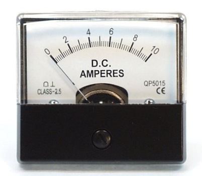
Ammeters
- 0-20A DC MU45 Amp Meter (ME1520)
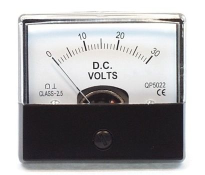
Voltmeters
- 0-30VDC MU45 Volt Meter (ME1535) – No longer available
Voltmeter vs Ammeter: The Bottom Line
Ammeters (A) are used for measuring the current. In contrast, voltmeters (V) measure the voltage between any two circuit points.
The resistance in an ammeter is low = 0, whereas in a voltmeter, it is high = infinity. Ammeters connect ‘in series’ with the circuit. Voltmeters connect ‘in parallel’’ with the circuit.
As for accuracy, ammeters are more accurate while voltmeters are less. The changing of range in A is not possible, but it is possible with V.
Moreover, measurements of V and I with standard voltmeters and ammeters alter the circuit being measured. This introduces uncertainties. Voltmeters draw some extra current, whereas ammeters reduce current flow.
© Electrotech Brands Pty Ltd 2022
Write a Comment
You must be logged in to post a comment.