

Student Multimeter Projects for School Electronics Classes
July 21, 2026
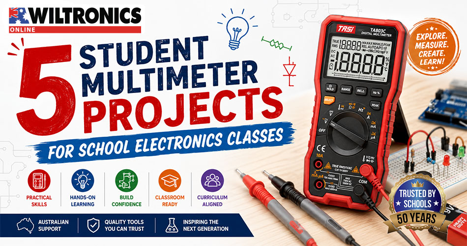
Student Multimeter Projects for School Electronics Classes
A multimeter helps students move beyond simply assembling circuits.
When an LED does not illuminate or a circuit behaves unexpectedly, students can measure what is happening rather than guessing. They can check a battery, verify a resistor, test a connection and follow the evidence towards a fault.
These skills support electronics, physics, engineering, STEM and technical-training activities. They also introduce a practical troubleshooting process that students can apply to increasingly complex projects.
Wiltronics supplies digital and analogue multimeters, multimeter leads and accessories and student bench meters for classroom, laboratory and workshop use. The current multimeter range includes both general-purpose models and more advanced instruments for technical measurement.
This guide features two Wiltronics TASI multimeters and five practical activities covering voltage, resistance, continuity, circuit behaviour and fault-finding.
Classroom safety: Complete these activities only with supervised, isolated, school-approved low-voltage circuits. Students should not test mains outlets, fixed wiring, switchboards or unknown electrical equipment.
Quick activity comparison
| Activity | Main meter function | Skill developed | Suggested level |
|---|---|---|---|
| Measure battery voltage | DC voltage | Polarity and probe placement | Beginner |
| Verify resistor values | Resistance | Component identification and tolerance | Beginner |
| Complete a continuity fault hunt | Continuity | Locating open connections | Beginner to intermediate |
| Compare series and parallel circuits | Voltage, with optional current | Circuit behaviour and meter placement | Intermediate |
| Troubleshoot a mystery circuit | Multiple functions | Evidence-based fault-finding | Intermediate to advanced |
Teachers can run the activities individually or combine them into a progressive measurement and troubleshooting unit.
Featured Wiltronics TASI multimeters
The Wiltronics TASI range provides two strong options for school electronics, technical education and workshop measurement.
TASI True RMS Auto-Ranging Digital Multimeter 600V
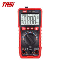
The TASI True RMS Auto-Ranging Digital Multimeter 600V is a practical general-purpose meter for circuit measurement and troubleshooting.
Auto-ranging simplifies setup by selecting an appropriate measurement range for the student. The meter includes a 9999-count backlit display and measures AC/DC voltage, AC/DC current, resistance, capacitance and frequency. It also provides continuity, diode testing, data hold and non-contact voltage sensing.
For classroom electronics, its most useful functions include:
- DC voltage
- DC current
- resistance
- continuity
- diode testing
- capacitance
This makes it well suited to breadboard circuits, component testing, battery checks and structured troubleshooting activities.
TASI Digital Multimeter 1000V High Precision

The TASI Digital Multimeter 1000V High Precision offers more detailed readings and a broader measurement set for senior electronics and technical training.
It features a 19999-count display, automatic and manual ranging, an analogue bar graph and relative-value mode. It measures voltage, current, resistance, capacitance, frequency and temperature.
Classroom applications can include:
- fine-resolution component measurements
- manual-ranging exercises
- temperature investigations
- capacitance and frequency activities
- observation of changing readings using the bar graph
- more advanced fault-finding
Both meters support measurements far above the levels required for these activities. Their maximum specifications are not suggested classroom operating voltages. Student projects should remain within approved, isolated low-voltage circuits.
Learn the meter before measuring
Before connecting a multimeter, students should be able to identify its main controls and terminals.
Most digital multimeters include:
- a display
- a rotary function selector
- a black COM terminal
- a voltage, resistance and continuity terminal
- a separate current terminal
- test probes
- function buttons such as hold or range
The black lead normally remains connected to COM. The red lead is placed in the voltage-and-resistance input for voltage, resistance, continuity and diode tests. It must be moved to the designated current input when measuring current.
Five questions to ask before every measurement
Students should pause and confirm:
- What electrical quantity am I measuring?
- Is the selector on the correct function?
- Are the leads connected to the correct inputs?
- Should the circuit be powered or unpowered?
- Does the meter connect across the circuit or become part of it?
Essential measurement rules
- Measure voltage in parallel across a component or source.
- Measure current in series so the circuit current passes through the meter.
- Measure resistance and continuity with circuit power removed.
- Never place a current-configured meter directly across a battery or supply.
- Inspect the meter and lead insulation before use.
- Hold probes behind their finger guards.
- Follow the instructions supplied with the specific meter.
Multimeter manufacturers emphasise identifying the function dial, COM terminal, voltage terminal and current terminal before testing, and prioritising correct setup to prevent equipment damage or electrical hazards.
Activity 1: Measure battery voltage
Battery testing provides an accessible introduction to DC voltage, probe polarity and recording units.
Students can compare labelled battery voltages with measured open-circuit readings using school-approved low-voltage cells.
Suggested equipment
- a Wiltronics multimeter
- assorted low-voltage batteries
- suitable battery holders and clips
- a recording sheet
- an optional low-current load circuit
Investigation question
How closely does the measured voltage of a battery match its labelled voltage?
Method
- Inspect the meter and leads.
- Connect the black lead to COM.
- Connect the red lead to the voltage-and-resistance input.
- Select DC voltage.
- Touch the black probe to the negative terminal.
- Touch the red probe to the positive terminal.
- Record the value and unit.
- Repeat with several batteries.
Students can reverse the probes for one measurement and observe the negative sign on the display.
This demonstrates that the meter reports both the size and polarity of the voltage.
Suggested results table
| Battery | Labelled voltage | Measured voltage | Probe direction | Observation |
|---|---|---|---|---|
| Battery A | Correct | |||
| Battery B | Correct | |||
| Battery C | Reversed |
Extension: voltage under load
A battery can produce one reading when disconnected and another while powering a circuit.
Students can compare:
- open-circuit battery voltage
- voltage while powering an approved load
- the difference between the two results
Ask students which measurement provides more information about how the battery performs during actual use.
Activity 2: Verify resistor values
Resistor testing connects colour-code identification with direct measurement.
Students first calculate a resistor’s nominal value from its coloured bands. They then measure the component and determine whether the result falls within its expected tolerance.
Suggested equipment
- a TASI digital multimeter
- 850-piece 5% carbon-film resistor pack
- a resistor colour-code chart
- calculators
- labelled component trays
The Wiltronics resistor pack contains a broad selection of values suited to identification, measurement and breadboard activities.
Investigation question
Does the measured resistor value fall within its stated tolerance range?
Method
- Select a resistor.
- Decode its nominal value.
- Identify the tolerance band.
- Calculate the acceptable upper and lower values.
- Confirm that the resistor is not connected to a powered circuit.
- Select resistance mode.
- Touch one probe to each resistor lead.
- Record the measured value.
- Compare the result with the expected range.
For a dependable component measurement, test the resistor separately or isolate it from other circuit paths.
Example tolerance calculation
For a 1000Ω resistor with a 5% tolerance:
- 5% of 1000Ω is 50Ω
- lower expected value is 950Ω
- upper expected value is 1050Ω
A measured result within this range is consistent with the stated tolerance.
Extension: analyse the class results
Students can test several resistors with the same nominal value and calculate:
- the difference from the nominal value
- percentage variation
- the average measured value
- the highest and lowest readings
- the proportion of components within tolerance
This creates a useful bridge between electronics, mathematics and data analysis.
Which TASI multimeter suits your classroom?
| Feature | TASI 600V True RMS | TASI 1000V High Precision |
|---|---|---|
| Display | 9999 count | 19999 count |
| Range selection | Automatic | Automatic and manual |
| True RMS | Yes | Not currently listed |
| Resistance range | Up to 100MΩ | Up to 20MΩ |
| Capacitance range | Up to 100,000µF | Up to 2000µF |
| Frequency range | Up to 10MHz | Up to 20MHz |
| Temperature measurement | No | -20°C to 1000°C |
| Analogue bar graph | No | Yes |
| Best fit | General classroom testing and troubleshooting | Senior electronics and technical training |
The TASI 600V auto-ranging multimeter is the more straightforward general-purpose option where everyday voltage, resistance, continuity and current measurement are the priorities.
The TASI 1000V high-precision multimeter is better suited to classes that can use manual ranging, finer display resolution, temperature measurement and additional analysis functions.
Activity 3: Complete a continuity fault hunt
Continuity mode helps students identify whether an electrical path is complete.
This makes it useful for locating open switches, disconnected wires, incorrect breadboard connections and missing circuit links.
Suggested equipment
- 830-point solderless breadboards
- 65-piece flexible jumper-wire packs
- switches
- low-voltage LEDs
- suitable resistors
- teacher-prepared fault circuits
The solderless breadboard and flexible jumper-wire pack provide a reusable platform for building and modifying classroom fault circuits.
Prepare the fault circuits
Create several unpowered circuits containing one deliberate fault, such as:
- a jumper in the wrong breadboard row
- an open switch
- a disconnected battery lead
- a missing power-rail link
- a loose connection
- a deliberately removed jumper
Investigation question
Where is the open connection preventing the circuit from working?
Method
- Disconnect the circuit from its supply.
- Inspect the circuit visually.
- Select continuity mode.
- Touch the probes together to confirm the function responds.
- Divide the circuit into logical sections.
- Test one section at a time.
- Record which paths have continuity.
- Narrow down the fault location.
- repair the connection.
- Reconnect the low-voltage supply and test the circuit.
Students should not probe points at random. Every test should reduce the number of possible fault locations.
Fault-finding record
| Test points | Expected result | Meter result | What the result suggests |
|---|---|---|---|
| A to B | Continuity | ||
| B to C | Continuity | ||
| C to D | Open circuit |
This activity introduces an important troubleshooting principle: each measurement should guide the next test.
Equipping an electronics or physics class? Contact Wiltronics to discuss TASI multimeters, classroom quantities, replacement leads and circuit-testing accessories.
Activity 4: Compare series and parallel circuits
Series and parallel investigations help students understand both circuit behaviour and correct meter placement.
Students can begin with voltage measurements. Current measurement can then be introduced as a teacher-led or intermediate-to-advanced extension.
Suggested equipment
- a school-approved low-voltage supply
- breadboards and prototyping equipment
- jumper wires
- resistors
- switches
- LEDs
- optional student bench meters
Part A: Measure voltage in a series circuit
Build a circuit containing two resistors in series.
Students measure:
- the supply voltage
- voltage across resistor one
- voltage across resistor two
They can compare the supply voltage with the combined voltage drops across the resistors.
Part B: Measure voltage in a parallel circuit
Rearrange the resistors into separate parallel branches.
Students measure the voltage across:
- the supply
- branch one
- branch two
Ask them to compare the results with those from the series circuit.
Intermediate extension: measure current
Current measurement requires a different circuit connection and additional care.
Before changing the setup:
- switch off or disconnect the supply
- move the red lead to the designated current input
- select the appropriate current function
- open the circuit at the chosen measurement point
- insert the meter in series
- check the arrangement
- briefly restore power and take the reading
- disconnect power before changing the circuit
- return the red lead to the voltage-and-resistance input when finished
Never connect a meter configured for current directly across a battery or power supply.
A useful classroom control is to have the teacher inspect every current-measurement setup before power is restored.
Student bench meter option
Analogue bench meters provide a dedicated, easy-to-view display for classroom demonstrations and permanent experiment stations.
The Wiltronics range includes instruments for specific current and voltage ranges, such as the 0–10V DC Student Bench Meter and 0–100mA DC Student Bench Meter. The broader category contains single-range, dual-range and centre-zero educational meters.
Handheld multimeters are more versatile, while bench meters can make changing circuit values easier for a group to observe.
Activity 5: Troubleshoot a mystery circuit
The final activity asks students to decide what to measure.
Instead of following a prescribed list of settings, each group receives a non-working low-voltage circuit and must diagnose the fault using evidence.
Possible hidden faults
- discharged or disconnected battery
- reversed LED
- incorrect resistor value
- open switch
- broken jumper wire
- missing ground connection
- component in the wrong breadboard row
- incorrect power-rail connection
- unintended short circuit
Troubleshooting process
Students should:
- inspect the circuit without changing it
- explain how the circuit should operate
- list one or more fault hypotheses
- select a meter function
- decide whether the circuit should be powered
- choose suitable test points
- take and record one measurement
- interpret the result
- decide what to test next
- locate, repair and explain the fault
Troubleshooting record
| Hypothesis | Meter function | Test location | Result | Conclusion |
|---|---|---|---|---|
| Battery voltage is too low | DC voltage | Battery terminals | ||
| Switch remains open | Continuity | Switch terminals | ||
| Wrong resistor fitted | Resistance | Isolated resistor | ||
| LED polarity is incorrect | Diode test | LED terminals |
Suggested assessment criteria
Assess students on:
- safe meter setup
- correct function selection
- appropriate probe placement
- logical test sequence
- accurate recording
- interpretation of evidence
- successful fault correction
- quality of explanation
The aim is not only to make the circuit work. Students should explain how their measurements identified the problem.
Common student multimeter mistakes
Leaving the red lead in the current input
After measuring current, the red lead should be returned to the voltage-and-resistance input.
A checkout card attached to each meter case can reinforce this habit.
Measuring resistance on a powered circuit
Power should be removed before resistance or continuity testing.
Connecting the meter across a supply in current mode
Current is measured by placing the meter in series. Connecting it directly across a source may blow a fuse or damage the meter.
Selecting AC instead of DC
Most battery-powered classroom circuits use DC. Students should check the selected symbol before testing.
Recording a number without its unit
A reading is incomplete without its unit and scale.
Students should record whether a measurement is in volts, millivolts, amps, milliamps, ohms, kilohms or megohms.
Testing too many things at once
One test or circuit change should be made at a time. Otherwise, students cannot determine which action revealed or corrected the fault.
Ignoring damaged leads
Cracked insulation, loose plugs or exposed conductors should be reported and removed from service.
The multimeter test-lead set with crocodile clips includes red and black leads, shrouded 4mm safety plugs, finger guards and compatible snap-on clips.
Handheld multimeters or student bench meters?
Both formats have useful classroom roles.
Handheld TASI multimeters
TASI digital multimeters suit:
- individual or paired practical work
- breadboard circuits
- battery testing
- component measurement
- continuity fault-finding
- senior electronics
- workshop troubleshooting
- technical-training activities
They allow several electrical quantities to be measured with one portable instrument.
Student bench meters
Dedicated bench meters suit:
- teacher demonstrations
- permanent experiment stations
- visible analogue movement
- introductory voltage and current comparisons
- circuits using banana-plug leads
- group observation
A classroom may use bench meters for foundational circuit demonstrations and TASI multimeters for component testing and independent fault-finding.
Test each meter before the lesson using an approved known component or voltage source. Confirm that the display, battery, leads and continuity function operate correctly.
For broader equipment planning, see Best Portable Measurement Tools for STEM, Workshops and Electronics. The guide covers current TASI portable measurement products and their applications across education, electronics and workshop testing.
Differentiating multimeter activities
Foundation level
Provide students with:
- a labelled meter diagram
- the required function
- the correct input terminals
- pre-selected test points
- a structured results table
Students focus on safe setup, probe placement and recording units.
Intermediate level
Provide the circuit and investigation question, but require students to select the function and measurement points.
Ask them to predict each result before testing.
Extension level
Provide a fault description without revealing the cause.
Students must create a troubleshooting plan, justify their test order and interpret the evidence.
Extension activities can include:
- calculating resistor percentage variation
- comparing theoretical and measured circuit values
- using relative-value mode
- measuring capacitance
- testing diode or LED forward voltage
- comparing automatic and manual ranging
- observing changing readings on an analogue bar graph
- designing a mystery circuit for another group
Frequently asked questions
Which TASI multimeter is best for school electronics?
The TASI 600V True RMS Auto-Ranging Multimeter is a strong general-purpose choice for voltage, current, resistance, continuity and component-testing activities.
The TASI 1000V High Precision model is more suitable where students can use finer resolution, manual ranging, temperature measurement and advanced functions.
Which multimeter functions should beginners learn first?
DC voltage, resistance and continuity are practical starting points.
They introduce correct function selection and probe placement without the additional circuit changes required for direct current measurement.
Can students measure current with a multimeter?
Yes, in suitable low-voltage circuits with direct supervision and a teacher-checked setup.
The meter must be inserted in series, and the leads must be placed in the correct inputs. Current measurement is best introduced after students are confident with voltage, resistance and continuity.
Why does the meter display a negative voltage?
A negative DC voltage normally means the probes are reversed relative to the source polarity.
This is a valid reading and provides useful information about direction.
Can a resistor be measured while it remains in a circuit?
Other paths through the circuit may affect the result.
For a more dependable component measurement, remove power and isolate at least one resistor lead where appropriate.
What does the continuity beep mean?
The beep indicates that resistance between the probes is below the meter’s continuity threshold.
It confirms a conductive path, but it does not necessarily prove that the connection will perform correctly while carrying its normal load.
Build confident circuit troubleshooters
Multimeter activities help students replace guesswork with evidence.
By measuring batteries, verifying resistors, testing connections and comparing circuits, students develop a clearer understanding of how electrical quantities relate to physical components.
A mystery-circuit challenge then brings those skills together. Students must select the right function, test logically and explain how each reading led them towards the fault.
Explore Wiltronics TASI and general-purpose multimeters, multimeter accessories and test leads and student bench meters for classroom circuits.
For assistance selecting TASI multimeters, replacement leads or quantities for your electronics program, contact the Wiltronics team.
© Electrotech Brands Pty Ltd 2026
Write a Comment
You must be logged in to post a comment.