

SPST, SPDT, DPDT Switches Explained: How to Choose
October 1, 2026
SPST, SPDT, DPDT Switches Explained: How to Choose
A switch can fit your enclosure perfectly and still be wrong for the circuit. It might spring back when you expected it to stay on, control one contact path when you need two, or carry an AC rating that does not establish suitability for your DC load.
Choose a switch by matching four things: contact arrangement, operating action, electrical rating and mounting dimensions. The actuator style—rocker, toggle or pushbutton—comes after those requirements.
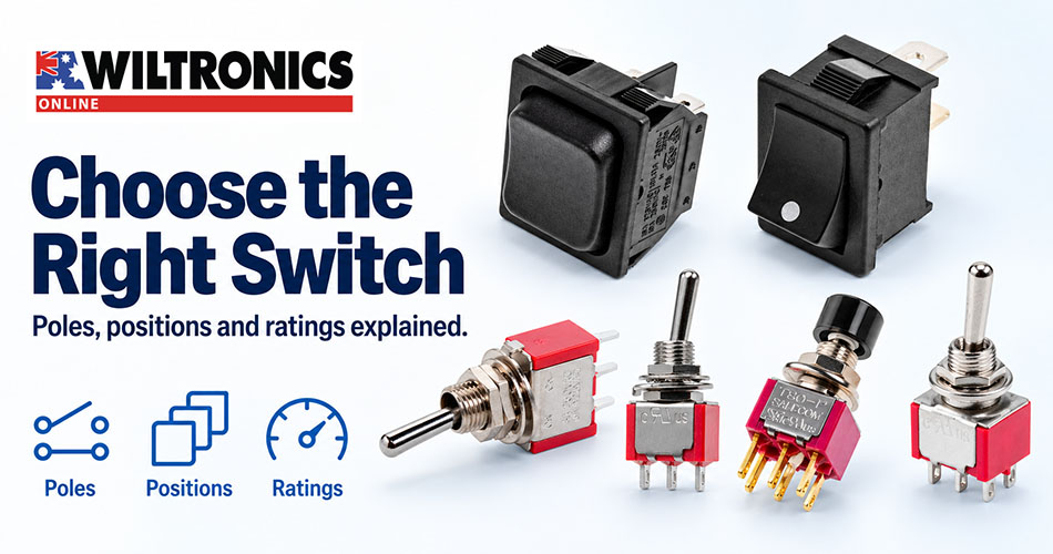
This guide explains the terminology and highlights six Wiltronics switches for different control arrangements.
1. What do SPST, SPDT, DPST and DPDT mean?
These abbreviations describe the switch’s contact arrangement.
A pole is an electrically separate contact path controlled by the switch. A throw is a connection that a pole can select.
| Type | Full name | What it does | Typical selection reason |
|---|---|---|---|
| SPST | Single pole, single throw | Opens or closes one path | Simple on/off control |
| SPDT | Single pole, double throw | Connects a common contact to either of two alternatives | Select between two paths |
| DPST | Double pole, single throw | Opens or closes two separate paths together | Switch two paths with one actuator |
| DPDT | Double pole, double throw | Changes two separate paths between alternative connections together | Two changeover functions operated together |
An SPDT switch does not necessarily have an off position. An ON–ON version selects one connection or the other, while an ON–OFF–ON version adds a centre-off position.
Likewise, DPDT does not tell you whether the switch stays in position or springs back. You need the operating-action specification as well.
Do not identify the arrangement solely by counting terminals. Illuminated switches can have extra connections for their lamp or LED.
2. Momentary versus maintained switches
A maintained switch stays in the selected position after you release it. This suits a control that should remain on until someone deliberately changes it.
A momentary switch returns to its resting position when released. This suits a temporary command, such as a test input or a function that operates only while held.
Toggle switches, rocker switches and pushbuttons can have different operating actions. Their appearance alone does not establish how they behave.
| Function marking | Typical behaviour |
|---|---|
| ON–OFF | Maintained on and off positions |
| ON–ON | Selects between two connections, without a designated off position |
| ON–OFF–ON | Two maintained on positions with centre off |
| (ON)–OFF–(ON) | Momentary operation in either direction, returning to centre off |
| ON–OFF–MOM | Maintained on in one direction, centre off and momentary operation in the other |
Parentheses commonly indicate a momentary position, while MOM means momentary. Wiltronics uses these conventions in its toggle-switch range. Always confirm the exact behaviour against the product description and contact diagram. www.wiltronics.com.au
A practical selection example
Suppose a low-voltage controller needs two temporary commands: increase and decrease.
An SPDT MOM–OFF–MOM switch is a candidate because it provides two momentary selections and returns to centre when released.
An SPDT ON–ON switch behaves differently: it remains in one selected position. Even though both switches are SPDT, they would produce different user controls.
The controller’s input requirements and the switch’s contact suitability still need to match.
3. Check the complete electrical rating
A marking such as “10A” is incomplete without the associated voltage, AC or DC designation, and load conditions.
AC and DC ratings are different
When contacts open, an arc can form between them. DC switching presents different conditions from AC switching, so you cannot assume that an AC current rating also applies to a DC circuit.
For a battery-powered project, look for an explicit DC rating suitable for the load. Omron’s technical guidance recommends selecting and using switches within their DC ratings when interrupting DC loads. components.omron.com
For example, a listing of 6A at 240V AC does not establish that the switch can interrupt 6A at 12V DC. Obtain the relevant DC specification before choosing it for that application.
Check what the switch is controlling
A resistive-load rating does not automatically cover a motor, solenoid or another load with different switching characteristics.
Consider normal operating current, start-up demand and the manufacturer’s applicable load ratings. If the load exceeds the switch’s capabilities, the circuit may need a suitable relay or electronic switching stage.
Very small signal currents deserve attention too. A switch intended for power loads may not be the best choice for a low-current electronic input. Check minimum-load specifications and contact suitability rather than selecting the highest current rating available. www.ia.omron.com
4. Check the panel fit before cutting
The visible bezel is usually larger than the mounting opening. Use the specified panel cut-out, not the switch’s overall face dimensions, when planning an enclosure.
Check:
- Panel thickness: the retaining clips or mounting thread must suit the material.
- Rear clearance: allow room for the body, terminals and connectors.
- Wire clearance: include space for insulation and comfortable wire bends.
- Assembly access: leave room to tighten a nut or release retaining clips.
- Actuator clearance: position the control where it can move freely and operate comfortably.
For a replacement switch, compare terminal locations and electrical function as carefully as the physical dimensions.
A switch that fits the old hole may still require a different wiring arrangement.
5. Confirm the contact behaviour before applying power
Use the contact diagram to identify each terminal. With the switch disconnected from every power source, a continuity meter can help verify which contacts connect in each position.
For a momentary switch, check both the held and released states. For a centre-off version, confirm that the intended paths open in the centre position.
Do not copy terminal positions from a similar-looking switch. Identify the contacts on the exact part you are installing.
This check can catch a mistaken operating action or terminal assumption before it becomes a circuit fault.
6. Wiltronics switch highlights
These six products illustrate different combinations of actuator style, contact arrangement and operating action.
SW3210: compact maintained on/off control
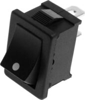
The SPST Mini Rocker Switch provides a straightforward maintained on/off action in a small panel footprint.
The listed rating is 19.5 × 13mm cut-out, spade terminals and a 6A at 240V AC rating.
It is worth considering when you need a compact rocker and a single switched path. Check rear clearance during enclosure planning, and obtain a suitable DC rating before selecting it for DC power switching. www.wiltronics.com.au
SW1514: two temporary commands from one toggle
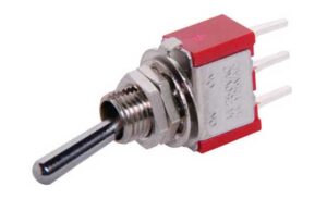
The SPDT Mini Toggle Switch MOM–OFF–MOM offers momentary operation in either direction with centre off.
Its listed contact rating is 2A at 250V AC or 28V DC for a resistive load.
Consider this action for a control interface requiring two temporary selections, such as increase/decrease commands. For electronic inputs, confirm suitability at the actual signal current as well as the maximum rating. www.wiltronics.com.au
SW1516: a maintained selection with a temporary alternative
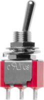
The SPDT Mini Toggle Switch ON–MOM combines one maintained position with a momentary alternative.
The listed rating is 2A at 250V AC or 28V DC for a resistive load.
This arrangement is useful when a circuit normally selects one path but needs to select another while the toggle is held. It does not provide the same centre-off behaviour as the SW1514. www.wiltronics.com.au
SW1525: maintained, off and momentary operation
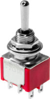
The DPDT Mini Toggle Switch ON–OFF–MOM combines two poles with three operating positions.
Its listed rating is 2A at 250V AC or 28V DC for a resistive load.
Consider it when two separate contact paths must change together and the interface needs maintained operation in one direction, centre off and momentary operation in the other. Check the contact diagram against the required behaviour in all three positions. www.wiltronics.com.au
SW2665: a rocker that returns to centre
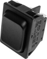
The DPDT Black Rocker Switch MOM–OFF–MOM provides momentary operation on either side and returns to centre when released.
It features snap-in panel mounting, spade terminals and a listed 29 × 22mm cut-out. Its published rating is 10A at 240V AC.
This is a rocker-style option for two momentary selections with two poles. Confirm an appropriate DC rating before using it to interrupt a DC load. www.wiltronics.com.au
SW0375: two changeover paths operated by a pushbutton
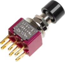
The DPDT Momentary Pushbutton Switch provides momentary operation with a DPDT contact arrangement.
Its listed rating is 0.5A at 250V AC or 28V DC for a resistive load.
It is worth considering when a press-to-operate interface needs to change two electrically separate paths together. Identify each common contact and its associated contacts before wiring. www.wiltronics.com.au
Your switch selection checklist
Before ordering, record the requirements in one place:
| Requirement | What to confirm |
|---|---|
| Contact arrangement | SPST, SPDT, DPST or DPDT |
| Operating action | Maintained, momentary or a combination |
| Positions | Whether a centre-off position is required |
| Electrical rating | Voltage, AC/DC, current and load type |
| Signal suitability | Minimum-load requirements where applicable |
| Mounting | Cut-out, panel thickness and rear clearance |
| Connections | Terminal type and contact diagram |
Explore Wiltronics’ rocker switches and industrial toggle switches, or use the individual product links above to compare the functions your project needs.
© Electrotech Brands Pty Ltd 2026
Write a Comment
You must be logged in to post a comment.