

Reflection and Refraction Experiments: A Practical Classroom Guide
October 16, 2026
Reflection and Refraction Experiments: A Practical Classroom Guide
A beam of light changing direction can catch students’ attention. Tracing its path, measuring angles and explaining the result turns that observation into a useful science investigation.
Reflection and refraction experiments give students a practical way to connect diagrams with real equipment. They also reveal common mistakes, particularly measuring angles from a surface instead of from the normal.
For Term 4 science, this guide offers two introductory ray-tracing activities, Wiltronics equipment highlights and practical troubleshooting advice. Adapt the activities to students’ experience and the instructions for your equipment.
Start with one narrow ray, mark the surface carefully and measure angles from the normal.
Reflection and refraction: what is the difference?
Reflection returns light into the medium it came from. Refraction occurs when light passes between media with different refractive indices; at oblique incidence, this generally changes its direction.
For these activities, the normal is a reference line drawn at 90° to the surface where the ray meets it.
| Feature | Reflection activity | Refraction activity |
|---|---|---|
| Main component | Plane mirror | Transparent rectangular block |
| Path to investigate | Incident and reflected rays | Incident, internal and emerging rays |
| Key observation | Reflection angle equals incidence angle | Direction changes at the block’s boundaries |
| Reference for angles | Normal to the mirror | Normal to the relevant block face |
A ray entering a transparent block along the normal does not bend away from its original direction. Use an oblique angle when first demonstrating the change in direction.
Prepare a clear ray-tracing station
For each working group, prepare:
- A suitable classroom light box or ray box with a single-slit arrangement.
- The specified compatible power supply.
- A plane mirror with a stable support.
- A transparent rectangular optical block.
- White paper, pencil, ruler and protractor.
- A recording sheet.
Test the setup before the lesson. Check that the ray crosses the paper clearly and strikes the optical component at the correct height.
Reduce ambient light enough to see the paths while keeping the workspace usable. Keep bright beams away from eyes and follow the manufacturer’s guidance on lamp heat, ventilation and power connections.
These activities use a classroom ray box. A laser is not required.
Activity 1: Measure the angle of reflection
Learning goal: use measurements to test the relationship between incident and reflected rays.
- Place the mirror upright on paper and mark the position of its reflecting surface.
- Direct a single narrow ray towards it at an angle.
- Mark two separated points along the centre of the incident ray and two along the reflected ray.
- Switch off the source before removing equipment to complete the drawing.
- Join the points with a ruler and locate the point of incidence.
- Draw the normal perpendicular to the mirror at that point.
- Measure both angles from the normal.
Repeat at three or more incident angles. Suitable starting targets might be 20°, 40° and 60°, adjusted to suit the equipment.
| Trial | Angle of incidence | Angle of reflection | Difference between readings |
|---|---|---|---|
| 1 | |||
| 2 | |||
| 3 |
The law of reflection predicts equal angles. Small differences in students’ readings should prompt discussion of alignment, beam width and marking accuracy.
Do not ask students to change their recorded results to match the prediction.
Teaching prompt: “What would happen to your measurements if you used the mirror surface as your reference instead?”
Activity 2: Trace light through a rectangular block
Learning goal: identify the changes in direction at two boundaries.
Place the block flat on paper and trace its outline. Aim the ray so it enters one long face obliquely and leaves the opposite parallel face, without reaching a corner.
- Mark two points along the incoming ray and two along the emerging ray.
- Keep the block fixed while marking.
- Switch off the source and remove the block.
- Extend the marked ray lines to the traced boundaries.
- Join the entry and exit points to reconstruct the path inside the block.
- Draw a normal at each boundary.
- Add arrows showing the direction of travel.
The internal ray may not be clearly visible in a clean transparent block. Reconstructing it from the entry and exit points is part of this method.
For light travelling from air into ordinary glass or acrylic at an oblique angle, the ray bends towards the normal. On leaving for air, it bends away from the normal.
With parallel faces and air on both sides, the emerging ray is parallel to the original incident ray, but is generally displaced sideways.
Ask students to distinguish parallel from following the same line.
Teaching prompt: “The ray emerges in the same direction. Does that mean it travelled straight through without changing direction?”
Turn ray diagrams into evidence
Ask each student to submit a diagram containing:
- The mirror position or block outline.
- Straight ray lines with direction arrows.
- A clearly labelled normal at each relevant boundary.
- Measured angles where requested.
- A short explanation supported by the drawing.
For students ready for an extension, repeat the block investigation at several incident angles. Keep the block and entry face consistent, then compare the emerging paths.
Begin with descriptions and diagrams. Introduce calculations such as Snell’s law only when they suit the learning objective.
Quick assessment: predict, label and explain
Finish with these three prompts:
- Draw and label the normal where a ray meets a plane mirror. If the incidence angle is 35°, predict the reflection angle and name the law you used.
- Use one pair of your recorded reflection angles to explain whether your measurements support the prediction. Suggest one source of measurement uncertainty.
- Sketch a ray entering and leaving opposite parallel faces of a rectangular block in air. Explain how the emerging ray can be parallel to the incident ray without following the same line.
Teacher check: Look for a perpendicular normal, a predicted reflection angle of 35°, evidence from actual readings, and a distinction between direction and sideways displacement.
Wiltronics equipment for classroom optics
IEC Hodson Light Box & Optical Set 12V
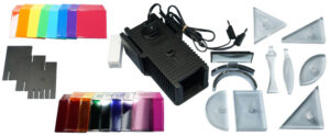
Our IEC Hodson Light Box & Optical Set—HL2060-001 supports foundational optics and colour investigations.
The listing includes mirrors, multiple slit formers, colour filters and plates. Operating instructions and an experimental manual are linked on the product page.
Check the kit contents and compatible power requirements when preparing class sets. A 12V light box must use the supply specified for the apparatus; it is not connected directly to mains power.
Rectangular Acrylic Prism
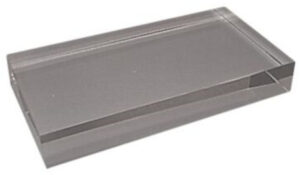
Our Rectangular Acrylic Prism—125 × 65 × 18mm provides an option for tracing refraction through a rectangular block.
Check that the block’s dimensions and the ray height suit your existing source. Position it so the beam enters and exits the intended parallel faces.
IEC Light Box Angular Scale for Rays
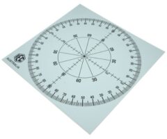
Our IEC Light Box Angular Scale for Rays—PA2060-090 is a 165 × 165mm accessory for measuring ray angles.
The listing states that it fits inside the kit housing and is not included in the standard Light Box kit.
It offers an alternative to measuring traced rays with a separate protractor. Students still need to identify the normal and use the correct angle reference.
Equilateral Triangular Glass Prism
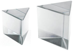
Our Equilateral Triangular Glass Prism is available in 38mm and 50mm sizes, with a 60°/60°/60° design.
Use it for a later comparison with the rectangular block. Its entry and exit faces are not parallel, so students should not expect the same emerging-ray geometry.
For white-light dispersion work, check the source, slit arrangement and screen position before planning the demonstration.
Common problems and practical checks
| Problem | What to check |
|---|---|
| Rays are difficult to trace | Ambient light, slit selection, focus and beam height |
| Reflection angles appear different | Normal placement, mirror alignment and ray-centre markings |
| A faint second reflection appears | Whether the mirror’s front glass surface produces an additional reflection |
| Refraction is difficult to observe | Whether the incident ray is too close to the normal |
| The emerging ray is not parallel in the block activity | Whether it crossed opposite parallel faces and the block stayed in its outline |
Where a mirror has a reflective coating behind glass, its effective reflecting surface is behind the front face. Use the apparatus instructions to position it correctly and discuss any resulting uncertainty.
Frequently asked questions
Do we need a laser for these activities?
No. Use a suitable classroom ray box with a single-slit arrangement.
Why measure angles from the normal?
The normal is the standard reference for both laws, allowing measurements to be compared consistently.
Does light always bend when entering glass?
No. At normal incidence, it continues in the same direction, although its speed changes.
Why does light leaving a rectangular block travel parallel to the incoming ray?
With air on both sides and parallel entry and exit faces, the two changes in direction cancel. The ray can still be displaced sideways.
Can we use a triangular prism instead of the rectangular block?
Use it as a separate investigation. Its angled faces change the geometry, so the rectangular-block prediction does not apply.
Prepare your next light investigation with Wiltronics
Explore our light and optics equipment for light boxes, mirrors, lenses, prisms and related teaching apparatus.
Give students time to predict the path, trace what happens and explain the difference. A carefully labelled ray diagram makes their reasoning visible.
© Electrotech Brands Pty Ltd 2026
Write a Comment
You must be logged in to post a comment.