

How to Crimp Insulated Wire Connectors: Butt, Ring and Spade Terminals
July 28, 2026
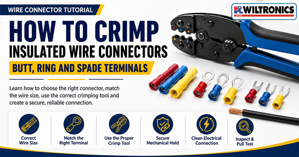
How to Crimp Insulated Wire Connectors: Butt, Ring and Spade Terminals
Insulated crimp connectors provide a quick and practical way to join wires or attach conductors to switches, terminal posts and other compatible equipment.
However, a reliable connection requires more than placing the terminal in a tool and squeezing the handles. The wire, connector and crimping die must match. The conductor also needs to be stripped cleanly, inserted fully and compressed in the correct part of the terminal.
A poorly made crimp can hide damaged strands, trapped insulation, inadequate compression or an incorrectly sized terminal.
This guide focuses specifically on pre-insulated butt splices, ring terminals, fork terminals and quick-connect spade terminals. For a broader introduction covering other crimping tools and applications, read the existing Wiltronics guide on how to use a crimping tool.
Browse Wiltronics’ ranges of electrical crimping tools and connectors and terminals for suitable electronics, workshop and low-voltage wiring projects.
Quick method: Select a terminal that matches the conductor size, strip enough insulation to fill the metal barrel, place the connector in the correct die, insert the wire fully, complete the crimp and finish with a visual inspection and pull test.
Electrical Safety Before Crimping
Disconnect and isolate every power source before cutting, stripping or crimping a wire.
Depending on the project, this may involve unplugging the equipment, disconnecting a battery or removing a low-voltage power supply. Take reasonable steps to prevent the circuit from being re-energised while work is underway.
Australian workplace guidance generally requires equipment to be de-energised before electrical work and states that electrical installation work should be carried out by licensed or registered electrical workers. Licensing requirements vary between states and territories.
Scope of this tutorial: The following steps are intended for suitable electronics, automotive accessory and extra-low-voltage projects. Do not use this guide as instructions for modifying fixed mains wiring.
What Is an Insulated Crimp Connector?
An insulated crimp connector contains a conductive metal barrel surrounded by an insulating sleeve.
The stripped conductor is inserted into the barrel. A compatible crimping die then compresses the barrel around the wire, creating both electrical contact and mechanical retention.
The coloured sleeve helps insulate the connection and often identifies the approximate conductor-size range.
A crimping tool must match the connector type. Tools intended for pre-insulated terminals produce a different crimp profile from tools designed for uninsulated lugs, bootlace ferrules, coaxial connectors or modular data plugs. Wiltronics lists these as separate crimping-tool applications.
Common Insulated Connector Types
| Connector | What it does | Common applications |
|---|---|---|
| Butt splice | Joins two conductors end to end | Wire extensions and cable repairs |
| Ring terminal | Secures a wire beneath a stud or bolt | Terminal posts, equipment connections and earth points |
| Fork terminal | Fits beneath a screw or clamp terminal | Terminal strips and control equipment |
| Quick-connect spade | Creates a removable blade connection | Switches, appliances, relays and automotive accessories |
| Heat-shrink butt splice | Joins two wires and adds an adhesive-lined sleeve | Suitable connections needing additional environmental protection |
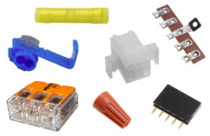
Wiltronics groups ring, fork, spade, blade, pin and butt-splice products within its wider connectors and terminals range.
Start by Matching the Connector to the Wire
Correct sizing is essential.
A connector that is too large may not grip the conductor securely. A connector that is too small may not accept all the strands or may be damaged during insertion.
Check:
- Conductor cross-sectional area
- Wire gauge
- Solid or stranded construction
- Terminal barrel range
- Cable insulation diameter
- Required stud or blade size
- Operating environment
- Compatibility with the crimping die
Match the Conductor, Not Just the Insulation
Two cables can have similar outside diameters while containing different amounts of conductor.
Thick insulation can make a small conductor look larger. Thin insulation can make a larger conductor appear smaller.
Use the conductor size printed on the cable or specified by its manufacturer rather than estimating from the outside diameter alone.
Red, Blue and Yellow Terminal Sizes
Many insulated terminals use red, blue and yellow sleeves to indicate different conductor ranges.
The standard Wiltronics insulated butt splice connectors and heat-shrinkable butt splice connectors use these listed ranges:
| Colour | Listed conductor range |
|---|---|
| Red | 0.25–1.65mm² |
| Blue | 1.04–2.63mm² |
| Yellow | 2.63–6.64mm² |
These ranges apply to the linked Wiltronics products. Check the packaging or technical information for the specific terminal being installed because manufacturers and connector systems may use different ranges.
Tools and Materials Required
A typical insulated-terminal job requires:
- Correctly sized crimp connector
- Compatible insulated-terminal crimper
- Wire stripper
- Wire cutter
- Suitable stranded wire
- Good task lighting
- Eye protection
- Heat gun for heat-shrinkable connectors
- Suitable test equipment where electrical checking is required
Recommended Crimping Products
| Requirement | Suitable option |
|---|---|
| Basic pre-insulated terminal work | Insulated Terminal Crimp Tool |
| Cutting, stripping and compatible crimping | Multi-Function Wire Stripper and Cutter |
| Interchangeable ratchet system | Quick-Change Ratchet Crimp Tool |
| Interchangeable terminal dies | Quick Interchangeable Crimp Tool Dies |
| Mixed connector projects | QC Crimp Connector Pack – 300 Pieces |
| Standard wire joining | Insulated Butt Splice Connectors |
| Adhesive-lined wire joining | Heat-Shrinkable Butt Splice Connectors |
The insulated-terminal tool is designed specifically for pre-insulated terminals. The interchangeable ratchet system supports separate dies for insulated terminals and several other connector systems. The mixed connector pack includes common ring, fork, bullet, spade and cable-joining terminals in multiple sizes.
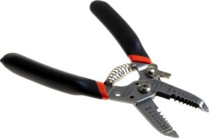
Browse wire strippers when choosing a tool that matches the conductor gauges used in your projects.
How to Crimp an Insulated Wire Connector
Step 1: Isolate the Circuit
Disconnect the circuit from every power source.
Do not assume that switching off a device has fully isolated the wire. Batteries, plug packs and other supplies may still energise parts of the equipment.
Secure the disconnected source where practical so it cannot be restored accidentally.
Step 2: Inspect and Cut the Wire
Inspect the cable before installing the terminal.
Cut back any section showing:
- Corroded conductor
- Burnt or brittle insulation
- Broken strands
- Severe flattening
- Previous stripping damage
- Chemical contamination
- Cracks or cuts
Use a suitable wire cutter to make a clean, square cut.
A crushed or angled end can make the conductor difficult to insert and may prevent the strands from filling the barrel evenly.
Step 3: Select the Connector and Die
Choose a connector that matches the conductor range and application.
Then select the matching cavity in the insulated-terminal crimper. Many tools identify the cavities using red, blue and yellow markings or conductor-size ranges.
Do not choose a die simply because the connector fits between the jaws. The die needs to produce the crimp profile intended for that terminal.
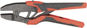
For regular work across several connector systems, an interchangeable ratchet crimping tool allows compatible dies to be changed for different applications.
Step 4: Determine the Strip Length
Inspect the terminal to estimate the length of its internal metal wire barrel.
Strip enough insulation for the conductor to fill that barrel without leaving an unnecessarily long section of bare wire exposed behind the connector.
A correctly prepared wire should allow:
- The conductor to reach the end of the wire barrel
- The cable insulation to meet the insulated support area
- All strands to remain inside the terminal
- Little or no unnecessary bare conductor behind the sleeve
For a butt splice, prepare each wire to fit within its own half of the connector.
Step 5: Strip the Insulation Cleanly
Select the stripping opening that matches the wire.
Place the conductor at the required strip length and remove the insulation in one controlled movement.
Inspect the exposed conductor immediately. It should have:
- Intact strands
- No deep scoring
- No missing strands
- No insulation trapped between strands
- A clean transition from insulation to conductor
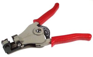
A dedicated wire stripper provides more control than cutting around the insulation with an ordinary knife.
Cut the end off and start again when strands have been seriously damaged.
Do not remove strands to force an oversized conductor into a smaller terminal.
Step 6: Position the Terminal in the Die
Open the crimping tool and place the connector’s metal barrel section in the correct die cavity.
Do not position the ring, fork, blade or other mating portion in the crimping area.
Keep the connector square to the jaws.
With a ratchet crimper, close the handles lightly until the die holds the terminal in position without fully compressing it. This can make wire insertion easier.
Check the tool instructions because terminal orientation can vary between crimp profiles.
Step 7: Insert the Wire Fully
Push the stripped conductor into the connector until it reaches the intended depth.
Check that:
- Every strand has entered the barrel
- No strand has folded backwards
- The conductor reaches the end of the barrel
- The insulation sits against or within the sleeve’s support area
- Bare copper is not excessively exposed
Keep the wire and terminal aligned.
A partly inserted conductor may appear secure while providing less mechanical retention and electrical contact than intended.
Step 8: Complete the Crimp
Close the tool handles using firm, steady pressure.
For a ratchet tool, continue until the mechanism completes its cycle and releases.
Do not deliberately stop halfway through the cycle. When the wire or terminal has moved out of position, use the tool’s release mechanism where provided and replace any connector that has been partly or incorrectly compressed.
Avoid:
- Crimping at an angle
- Placing the die outside the metal barrel
- Crushing only the coloured sleeve
- Hammering the terminal
- Repeatedly squeezing random parts of the connector
- Using a die intended for a different terminal system
Do not use ordinary pliers for standard pre-insulated butt, ring, fork or spade terminals. Use the correct crimping die unless the connector manufacturer specifically states that pliers are suitable.
Step 9: Inspect the Connection
A visual inspection can identify many common failures.
Look for:
- A centred crimp impression
- A straight terminal body
- Undamaged insulation
- No loose strands
- No split sleeve
- No conductor entering the mating area
- Minimal exposed copper
- No badly crushed cable insulation
The terminal should not rotate freely around the conductor.
Step 10: Perform a Pull Test
Hold the terminal and insulated wire securely.
Apply a firm, steady pull in line with the conductor. Avoid jerking the wire or bending it sharply during the test.
The conductor should remain fixed inside the terminal.
When the wire moves or pulls out, cut off the connector and repeat the process with a new terminal. A crimped terminal should not be reused.
Where appropriate, finish with a de-energised continuity or connection check. Remember that electrical continuity alone does not prove the mechanical crimp is secure.
How to Crimp a Butt Splice Connector
A butt splice joins two wires end to end.
Use this process:
- Isolate the circuit.
- Cut both conductors cleanly.
- Select a butt splice that matches the wire sizes.
- Strip each conductor to the required length.
- Insert the first wire fully.
- Crimp the first side.
- Inspect and pull-test it.
- Insert the second wire from the opposite end.
- Crimp the second side.
- Inspect and test the completed splice.
Do not attempt to crimp both sides of the connector with one off-centre compression.
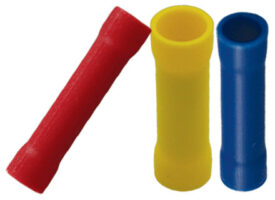
Wiltronics’ standard butt splice range uses tin-plated copper barrels with vinyl insulation and is available in red, blue and yellow conductor ranges.
How to Crimp Ring and Fork Terminals
Ring and fork terminals connect a wire to a compatible threaded post, stud or screw terminal.
In addition to the conductor size, check the terminal opening.
Ring Terminals
A ring terminal must fit over the intended stud without excessive movement.
It is commonly selected where the fastener passes completely through the terminal, creating a connection that cannot be removed without loosening or removing the fastener.
Fork Terminals
A fork terminal slides beneath a compatible screw or clamp.
It can be convenient where the screw does not need to be removed completely, but the fork and fastener must be compatible with the intended equipment.
Before crimping either style, confirm:
- Conductor range
- Stud or screw size
- Insulated-terminal construction
- Crimping-die compatibility
- Suitability for the equipment and environment
Browse ring and forked terminals for standard, uninsulated and heat-shrinkable options in several sizes.
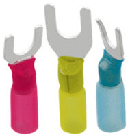
The crimp itself follows the same core process: strip the wire, position the barrel in the correct die, insert the conductor fully, complete the crimp, inspect it and perform a pull test.
How to Crimp Quick-Connect Spade Terminals
Quick-connect spade terminals create a removable blade-style connection.
Before installation, check:
- Male or female configuration
- Blade width
- Conductor range
- Insulated or uninsulated design
- Compatible crimping tool
- Temperature and environmental requirements
After crimping, test both parts of the connection.
The terminal should retain the wire securely and mate firmly with the matching blade without feeling loose or requiring unreasonable force.
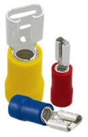
Explore quick-connect spade terminals for several blade sizes and terminal configurations.
How to Finish a Heat-Shrinkable Butt Connector
A heat-shrinkable butt splice combines a crimp barrel with an adhesive-lined outer sleeve.
The barrel must still be crimped correctly before heat is applied.
After crimping both sides:
- Inspect and pull-test the connection.
- Place it on a heat-resistant surface.
- Use a suitable heat gun.
- Begin with controlled heat.
- Keep the heat source moving.
- Rotate the connection where safe.
- Stop when the sleeve has recovered evenly.
- Allow the connector to cool.
- Inspect for splits, scorching or incomplete recovery.
Do not use heat shrinking to conceal or compensate for a loose crimp.
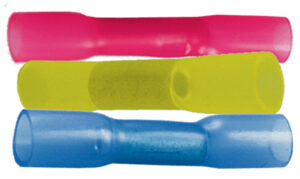
Wiltronics’ heat-shrinkable butt splice connectors use a polyolefin heat-shrink sleeve with an adhesive seal and are offered in the same three conductor ranges as the standard butt connectors.
For more information about recovered diameter and controlled heating, see the heat shrink tubing size guide.
What Does a Good Crimp Look Like?
| Good crimp | Poor crimp |
|---|---|
| Connector matches conductor size | Terminal is too large or too small |
| Wire is fully inserted | Conductor stops partway into the barrel |
| Strands remain intact | Strands are cut, missing or folded backwards |
| Crimp is centred on the barrel | Crimp impression is outside the barrel |
| Terminal remains straight | Terminal is bent or twisted |
| Sleeve is intact | Insulation is split or crushed |
| Minimal bare conductor is visible | Excess copper is exposed |
| Terminal passes a pull test | Wire moves or pulls out |
A good-looking connection can still fail when the wrong terminal or die has been used. Always combine visual inspection with a pull test.
Common Crimping Mistakes
Choosing by Cable Diameter Alone
Match the terminal to the conductor size, not merely the outside insulation diameter.
Using the Wrong Die
Pre-insulated terminals, uninsulated lugs and ferrules require different crimp profiles.
Use the cavity intended for the connector being installed.
Stripping Too Much Insulation
Excessive strip length can leave exposed copper behind the terminal and reduce insulation support.
Stripping Too Little Insulation
When insulation enters too far into the conductor barrel, the crimp may compress plastic rather than gripping the conductor correctly.
Damaging the Strands
Cut or deeply scored strands reduce the amount of conductor inside the connection.
Prepare a new wire end when stripping has caused meaningful damage.
Removing Strands to Make the Wire Fit
Do not reduce the conductor manually to fit an undersized terminal.
Select the correct connector.
Inserting the Wire Partway
Push the conductor fully into the barrel before completing the crimp.
Crimping Only the Plastic Sleeve
The die must form the underlying metal barrel around the conductor.
A visible dent in the coloured insulation does not necessarily mean the electrical crimp is correct.
Recrimping Randomly
Repeated compression can damage the terminal and create an unpredictable result.
Use one correctly positioned crimp unless the connector instructions specify separate crimping zones.
Skipping the Pull Test
A simple pull test can reveal incorrect sizing, incomplete insertion and poor compression before the cable is installed.
Reusing a Terminal
A crimp permanently deforms the barrel.
Use a new connector after a failed or removed crimp.
Other Connector Types Need Different Tools
This tutorial covers common pre-insulated wire terminals.
Do not apply the same die and method automatically to:
- Bootlace ferrules
- Uninsulated cable lugs
- RJ11, RJ12 or RJ45 plugs
- Coaxial connectors
- Deutsch contacts
- Molex-style contacts
- Heavy battery lugs
- Insulation-displacement connectors
Each system can require different strip lengths, dies and crimp profiles.
| Connector system | Typical tool |
|---|---|
| Red, blue and yellow insulated terminals | Insulated-terminal crimper |
| Uninsulated ring or fork lugs | Uninsulated-lug crimper |
| Bootlace ferrules | Ferrule crimper |
| RJ modular plugs | Compatible modular plug crimper |
| Coaxial connectors | Matching hex or compression tool |
| Specialist removable contacts | Connector-specific contact crimper |
| Heavy cable lugs | Heavy-duty lug crimper |
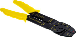
Browse the broader crimping tools and die range when working with more than one connector system.
Insulated Crimping Checklist
Before Crimping
- Circuit is isolated
- Wire is in serviceable condition
- Connector matches the conductor size
- Terminal style suits the connection
- Die matches the terminal
- Wire is cut squarely
- Strip length has been checked
- Conductor strands are undamaged
During Crimping
- Terminal is square in the die
- Metal barrel is in the crimping area
- Wire is fully inserted
- No strands remain outside the barrel
- Cable insulation meets the support area
- Tool completes its intended cycle
After Crimping
- Crimp impression is centred
- Terminal remains straight
- Sleeve is undamaged
- Bare copper is not unnecessarily exposed
- Wire passes a steady pull test
- Mating terminal fits correctly
- Electrical checks are completed while de-energised
- Heat-shrink sleeve is recovered evenly where applicable
Frequently Asked Questions
Can I crimp standard wire terminals with ordinary pliers?
Ordinary pliers should not be used for standard pre-insulated butt, ring, fork or spade terminals.
Use the correct crimping die unless the connector manufacturer specifically states that pliers are suitable.
How much insulation should I strip?
Strip enough insulation for the conductor to fill the terminal’s metal barrel.
Avoid leaving an excessive length of bare copper behind the insulated sleeve.
Should bare copper be visible after crimping?
A small inspection area may be visible on some terminal designs.
A long section of exposed conductor behind an insulated terminal usually indicates excessive strip length or incomplete insertion.
Why does the wire pull out?
Common causes include:
- Terminal too large for the conductor
- Wrong crimping die
- Incomplete compression
- Wire not fully inserted
- Insulation trapped in the barrel
- Damaged conductor strands
- Terminal positioned incorrectly
Cut off the failed connector and repeat the process with a new terminal.
Can a crimp connector be reused?
No. Crimping permanently deforms the metal barrel.
Should stranded wire be twisted before crimping?
Gently gather loose strands so they enter the terminal together.
Do not remove strands or change the conductor preparation unless the terminal manufacturer specifies it.
Should solder be added after crimping?
A correctly selected and applied crimp should be completed according to the connector manufacturer’s instructions.
Do not add solder simply to compensate for a loose or incorrectly sized crimp.
Do heat-shrink butt connectors still need to be crimped?
Yes.
The internal metal barrel must be crimped around the conductor before the outer sleeve is heated.
Are all red, blue and yellow terminals identical?
No.
The colours commonly identify conductor ranges, but exact dimensions and specifications can vary. Check the relevant product information.
Can this process be used on fixed mains wiring?
This guide is intended for appropriate electronics and extra-low-voltage projects.
Fixed electrical installation work must be handled by an appropriately licensed or registered electrical worker where required.
Create Cleaner, More Reliable Crimp Connections
A dependable crimp begins before the handles close.
Match the terminal to the conductor size, use the correct die, strip the wire without damaging its strands and insert the conductor fully into the metal barrel. Complete a correctly positioned crimp, inspect the connection and perform a pull test before installation.
Explore Wiltronics’ selection of electrical crimping tools, wire strippers, butt splice connectors, ring and fork terminals and quick-connect spade terminals for your electronics bench, workshop or low-voltage wiring project.
© Electrotech Brands Pty Ltd 2026
Write a Comment
You must be logged in to post a comment.