

Choosing Digital Callipers for Electronics Projects
September 22, 2026
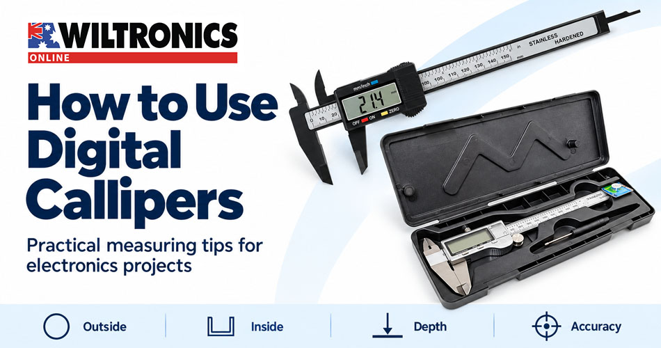
Choosing Digital Callipers for Electronics Projects
Will a connector fit through that panel? Is a replacement spacer the right length? How far apart are the mounting holes on an unlabelled circuit board?
Digital callipers help answer the small dimensional questions that can otherwise lead to the wrong part or an unnecessary cut. They are useful for electronics assembly, repairs, model making and workshop projects—but a detailed display still needs careful interpretation.
This guide explains which specifications matter, how the main measurement functions work and how to turn a reading into a useful decision.
Quick answer: Choose callipers with the range and jaw access your project requires, then check their documented accuracy separately from display resolution. Clean the contact surfaces, check zero and repeat measurements with light, consistent pressure before using the result.
1. Resolution, accuracy and repeatability are different
A display that changes in 0.01mm steps does not automatically measure accurately to ±0.01mm.
| Term | What it tells you | What it does not establish |
|---|---|---|
| Resolution | The smallest displayed increment | The maximum error in a measurement |
| Accuracy specification | The manufacturer’s stated measurement-error limits under defined conditions | Performance outside those conditions |
| Repeatability | How closely repeated measurements agree under the same conditions | Whether those readings are close to the true dimension |
For example, several similar readings can all include the same zero offset. A stable number is useful, but it is not proof of accuracy.
If a part must meet a tight tolerance, obtain the instrument’s accuracy specification and appropriate calibration information. Neither the word “precision” nor the number of decimal places is enough to establish suitability.
2. Match the range and measuring surfaces to the job
A 150mm range covers many small components and assemblies. However, the jaws must also reach the feature you want to measure. A recessed part, deep bore or obstructed mounting point may require a different instrument even when its nominal dimension is below 150mm.
Typical four-way callipers offer the following functions:
| Measurement | Measuring feature | Project example |
|---|---|---|
| Outside | Large lower jaws | Spacer length, shaft diameter or panel thickness |
| Inside | Small upper jaws | An accessible slot or opening |
| Depth | Extending depth rod | A recess or blind hole |
| Step | Rear step-measuring faces | Height difference between two accessible surfaces |
Check the exact model’s features before buying. Mitutoyo’s measuring-instrument fundamentals explains the outside, inside, step and depth functions used on conventional callipers.
3. Compare Wiltronics’ 150mm digital callipers
Wiltronics lists the following two models. Their material, controls and documented features provide a more useful comparison than their product names alone.
| Feature | TL2083 | TL2081 |
|---|---|---|
| Product | Digital Vernier Calipers 150mm | Precision Digital Vernier Caliper 150mm |
| Listed range | 0–150mm | 0–150mm / 0–6in |
| Material | Hardened stainless-steel frame and jaws | Carbon-fibre-reinforced plastic |
| Listed resolution | 0.01mm | Description states 0.01mm; confirm documentation for precision work |
| Notable features | Thumb-roll adjustment, locking screw, depth rod and floating zero | Metric/imperial switching, inside/outside measurement and depth gauge |
TL2083: stainless-steel construction and adjustment controls
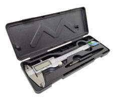
The TL2083 is worth considering when you want a metal frame with thumb-roll adjustment and a locking screw. Wiltronics also lists four-way measurement, large 11mm display digits and 0.01mm repeatability.
The reviewed page specifies metric operation and an SR44 battery. Check unit-switching requirements before ordering rather than assuming every digital model offers the same controls. Its resolution and repeatability figures should not be treated as a separate guaranteed accuracy specification.
TL2081: reinforced-plastic construction and unit switching
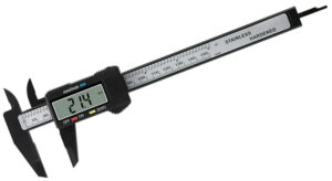
The TL2081 offers reinforced-plastic construction and metric/imperial selection. Its depth gauge adds another measurement option alongside the jaws.
The listing uses “±0.01mm” under its resolution heading. Because resolution and accuracy are different quantities, confirm the manufacturer’s documentation if you need a stated error limit. Do not infer an accuracy advantage from that notation or from the model’s “Precision” title.
4. Use a simple measurement routine
- Clean the contact areas. Remove debris from the measuring faces and the part. A trapped particle changes what the jaws contact.
- Check movement and zero. The slider should move smoothly. Close the clean jaws gently and check the display, following the instrument’s zero-setting instructions.
- Align the tool. Seat the measuring faces against the intended surfaces without tilting them.
- Use light, consistent pressure. Avoid squeezing the part or forcing the slider.
- Repeat after repositioning. Release and measure again. Investigate changes rather than selecting whichever number looks most convenient.
Mitutoyo’s calliper measurement guidance stresses alignment, light measuring force and repeated readings. A zero check is a useful starting check; it does not verify accuracy throughout the measuring range.
5. Measure the feature you actually need
Outside dimensions
Use the large jaws for a part’s width, thickness or outside diameter. Check that they contact the intended surfaces rather than a raised marking, burr or moulding seam. On soft cable jackets or flexible parts, watch for deformation under pressure.
For cable-entry planning, measure the cable’s overall outside diameter, including its jacket. Compare that with the specified cable range of the cable gland, while checking panel-hole and installation requirements separately. The conductor size printed on a cable is a different measurement.
Inside dimensions
Use the upper jaws for an accessible opening. For a circular hole, the contacts must span its diameter rather than a shorter off-centre chord. Small holes, chamfers and the shape of the jaw tips can limit how well the tool reaches the feature. Use the component drawing or a more suitable gauge when the fit is critical.
Depth and steps
For depth, place the reference end flat on the surrounding surface and extend the rod gently to the bottom. Make sure it reaches the intended bottom surface rather than debris or a sloping edge.
For a step, use the dedicated rear faces where provided. These give a reference for the difference between two levels. Keep both contacts properly seated before reading.
6. Worked example: finding mounting-hole spacing
Hole centres can be awkward to locate directly with ordinary jaws. For two equal, round holes, you can calculate their centre spacing from their edge-to-edge span and diameter.
Centre spacing = far-edge-to-far-edge span − hole diameter
Suppose an accessible pair of holes gives these illustrative measurements:
| Measurement | Example value |
|---|---|
| Span between the two farthest hole edges, measured along the line joining their centres | 43.20mm |
| Diameter of each hole | 3.20mm |
| Calculated centre spacing | 40.00mm |
The arithmetic is 43.20 − 3.20 = 40.00mm. You can cross-check using the gap between the nearest edges: that gap plus one hole diameter should give the same centre spacing.
This method assumes equal circular holes and correct alignment. Slots, damaged holes and countersinks need a different approach. Measurement errors also carry through the calculation; the displayed decimal places do not make the result exact.
Use the result to check a mounting drawing or trial layout before drilling. A measured dimension and a design’s required clearance are separate decisions.
7. Keep a ruler for the jobs that suit it
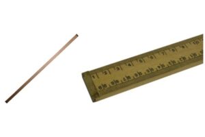
Callipers complement a ruler. For rough layout, checking available space or marking a straightforward length, a wooden ruler provides a simple reference without batteries.
Choose the tool around the decision: checking whether a board is roughly 100mm long is different from assessing whether a replacement shaft will fit a mating part. A ruler is also useful for an initial sense-check if a digital reading looks unexpected.
8. Protect the tool between projects
Wipe the tool after use and protect its measuring faces from impact and workshop debris. Follow its instructions for storage, battery changes and cleaning products.
Do not use the jaws as a clamp or scribing tool. If the callipers are dropped, the slider jams or zero becomes inconsistent, investigate before relying on them. Mitutoyo’s instrument care guide highlights clean measuring faces, smooth movement and checking for damage.
Before-you-buy checklist
- Is the measuring range large enough for the intended parts?
- Can the jaws or depth rod reach the actual feature?
- Do you need metric readings, imperial readings or both?
- Is accuracy documented separately from resolution?
- Do the material and controls suit your work?
- Is the tool suitable for the environment in which you will use it?
- For tight tolerances, do you have an appropriate verification or calibration method?
Measure with the next step in mind
A useful measurement helps you choose a part, check a fit or plan a modification. Match the tool to the feature, take time over alignment and keep display resolution in perspective.
Explore measuring tools at Wiltronics and compare the TL2083 stainless-steel callipers with the TL2081 reinforced-plastic model for your next electronics or workshop project.
© Electrotech Brands Pty Ltd 2026
Write a Comment
You must be logged in to post a comment.