

Breadboard Circuit Not Working? How to Find the Fault
September 28, 2026
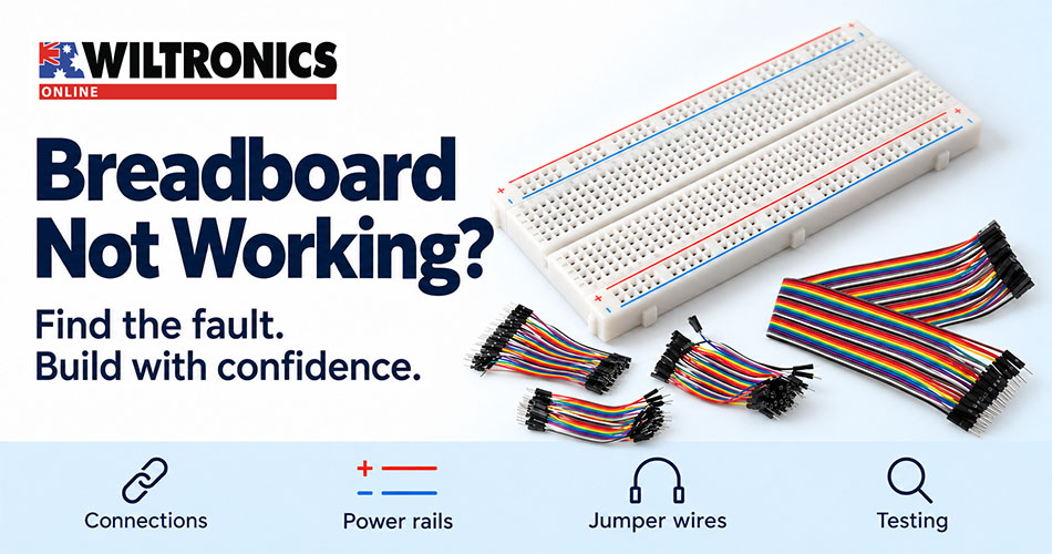
Breadboard Circuit Not Working? How to Find the Fault
An LED stays dark. A sensor stops responding. A circuit works until you move it. Before replacing parts or rewriting the program, check the connections between them.
A solderless breadboard makes experiments easy to change, but its hidden contacts can also hide mistakes. One misplaced jumper can leave a component disconnected even when the layout looks almost identical to the instructions.
Start here: Disconnect power before changing wiring. Check the breadboard connections, trace the circuit and inspect the jumpers. Then reconnect power for a voltage check at the circuit itself. Change one thing at a time so you can identify what fixed the fault.
1. Start with the symptom
Write down what you expected and what actually happened. “It does not work” gives you fewer clues than “the power indicator lights, but the external LED stays off”.
| Symptom | First checks | What to try next |
|---|---|---|
| Nothing operates | Supply connection, voltage setting and polarity | Measure the supply at the circuit’s power and ground connections |
| One section works, another does not | Separate rails, missing links or a misplaced ground wire | Trace the supply and return path to the failing section |
| Operation changes when the board moves | Loose jumper, damaged contact or unsupported module | With power disconnected, substitute one lead or move the connection |
| An LED stays off | LED orientation, series resistor and breadboard rows | Check the complete current path |
| A module powers up but sends no useful data | Pin assignments, signal wiring and logic compatibility | Compare the exact module pinout with the program |
These checks identify starting points, not guaranteed diagnoses. A wiring fault and a software fault can produce similar symptoms.
2. Understand the contacts beneath the holes
On a typical breadboard, the central terminal area contains groups of five connected holes. The centre channel separates the groups on opposite sides. Power rails run along the edges, but their arrangement varies: opposite rails are not automatically joined, and some rails have a break partway along.
The printed red and blue lines are guides. They neither supply power nor prove electrical continuity.
With the board disconnected from all power sources, use continuity mode to map an empty breadboard or isolated section. Check the holes you intend to use rather than relying on appearance. Other components can create alternative paths during an in-circuit test, so disconnect them when the result is ambiguous.
Adafruit’s Breadboards for Beginners provides illustrated explanations of the internal contact arrangement.
Practical check: Both legs of an LED or resistor placed in the same connected group share the same electrical node. Moving the component a little may be necessary to put its ends on separate nodes.
3. Trace the circuit by connection, not appearance
A diagram shows electrical relationships. Your physical layout can look different and still be correct—or look similar while connecting the wrong holes.
Make a short connection list before troubleshooting a complicated build. For a basic LED circuit, list the path from supply positive through the resistor and LED to supply negative. The worked example below shows how to check this path.
Follow each path with power disconnected. Read row numbers closely and check both ends of every jumper. A lead inserted one row away from the intended connection can look convincing from above.
For modules, read the labels on the actual board. Similar-looking sensor boards can have different pin orders. Also distinguish a connector’s physical pin position from the GPIO number or board label used by the program.
Take a clear overhead photograph before changing several connections. It gives you a record of the starting layout and helps you compare the build with your connection list.
4. Inspect the jumpers and contacts
If a connector fits loosely, replace the lead or test another contact position. Repeatedly pushing or bending it until the circuit briefly works leaves the underlying fault unresolved. Do not force oversized leads into a breadboard contact.
With power disconnected, check that each pin is fully seated and that a nearby cable is not pulling it sideways. Substitute one suspect lead with a known-good lead, then test again.
5. Check power where the circuit receives it
A power indicator on the controller does not prove that the external module receives its required supply.
After checking the wiring, use the appropriate DC voltage range and measure between the circuit’s supply and ground connections. Compare the reading with the component’s documented operating range. For this parallel voltage measurement, use the meter’s COM and voltage terminals—not its current input.
Check the ground path as carefully as the positive connection. Ordinary non-isolated logic connections usually need a shared reference between the controller and module; follow the board documentation when separate supplies or isolation are involved.
Keep 3.3V and 5V requirements distinct. A module’s supply rating does not necessarily tell you what voltage its signal pins accept. A jumper wire does not convert logic levels.
Use this guide for low-voltage prototypes. Solderless breadboards and general jumper leads are not a basis for mains wiring or an assumed high-current power path. Disconnect power before moving components, and use continuity or resistance mode only on a de-energised circuit with stored charge discharged.
6. Worked example: an LED that stays dark
Consider a simple test circuit with a regulated 5V supply, a suitable red LED and a 1kΩ series resistor. This example uses the supply directly, not a microcontroller output pin.
Assuming an LED forward voltage of 2V, the estimated current is:
Current = (5V − 2V) ÷ 1,000Ω = 0.003A, or 3mA.
Actual LED voltage and brightness depend on the component, so confirm its specifications. The resistor limits current and must remain in series.
If the LED does not light:
- Disconnect power and check LED polarity using its datasheet or reliable package markings.
- Confirm that its two legs occupy different connected groups.
- Trace the positive supply through the resistor and LED back to supply negative.
- Check any rail break along that path.
- Reconnect power and verify the voltage at the circuit’s supply points.
- If necessary, disconnect power again and substitute one suspect jumper with a known-good lead.
Change one thing per test. If you reverse the LED, replace three wires and change the program simultaneously, a working circuit will not tell you which fault you found.
7. Separate wiring faults from software faults
Once supply and connections check out, reduce the program to the smallest test that exercises the failing function. Confirm that the selected pin in the code matches the physical connection.
For a button or other digital input, check how the input obtains a defined state when the switch is open. An undriven input can produce unstable readings. Pull-up or pull-down arrangements depend on the board and circuit; match the program to the wiring.
Record three things for each test: the change made, the expected result and the observed result. This simple log is especially useful when a fault appears intermittently.
8. Choose leads that make troubleshooting easier
Match the ends to the connection
“Jumper wire” describes several products. Choose the termination at each end by looking at the mating connection.
| Connection you need | Typical lead type |
|---|---|
| Breadboard hole to another breadboard hole | Male-to-male |
| A board’s female header socket to a breadboard | Male-to-male |
| A module’s exposed male header pin to a breadboard | Male-to-female |
| Exposed male header pins on both boards | Female-to-female |
These examples assume compatible connector dimensions. A connector that fits mechanically does not establish correct voltage, polarity or signal compatibility.
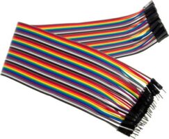
Wiltronics’ 40-pack jumper connector leads offer all three termination combinations in 100mm, 200mm and 300mm lengths. The rainbow strips can stay grouped or separate into individual leads.
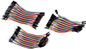
For a bench that regularly switches between different boards, the jumper lead set of 3 × 40 packs includes male-to-male, male-to-female and female-to-female strips. Select the length appropriate to the layout; the set contains 120 leads in total.
Match the wire style to the layout
Preformed solid jumpers suit short connections within the breadboard. Flexible leads suit connections between the breadboard and separate modules. Using each where it fits best can make a circuit easier to inspect.
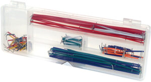
| Wiltronics product | Listed features | Where it can help |
|---|---|---|
| MA4020 140 Piece Breadboard Jumper Kit | Preformed 22 AWG solid wire; ten pieces in each of fourteen lengths; storage case | Short links between nearby breadboard connections |
| MA3020 Flexible Breadboard Jumper Wires | Male pins at both ends, flexible stranded cores and assorted colours and lengths | Connections that need to reach around components or between boards |
| MA4009 830-point Breadboard | 630 terminal points plus two 100-point sections; 165 × 56 × 10mm | A larger prototyping area when the existing layout is crowded |
Choose enough cable length to reach without tension. Avoid unnecessary loops that cover component labels or make it hard to see where a wire ends.
9. Know when to move beyond the breadboard
A breadboard is useful while you are exploring and changing a circuit. If the project will be handled regularly, installed in an enclosure or exposed to vibration, plan connections with suitable mechanical retention.
Save the verified schematic and pin map before moving to a soldered prototype or PCB. Recheck the finished assembly rather than assuming that copying a working layout guarantees a working build.
Build a troubleshooting kit around your projects
Keep a few known-good leads separate from your general supply so you have dependable substitutes during fault finding. Add preformed jumpers for short links and flexible leads with the terminations your modules require.
Explore Wiltronics jumper wires and breadboards to put together a setup that is easier to build, inspect and troubleshoot.
© Electrotech Brands Pty Ltd 2026
Write a Comment
You must be logged in to post a comment.