

October 20, 2026
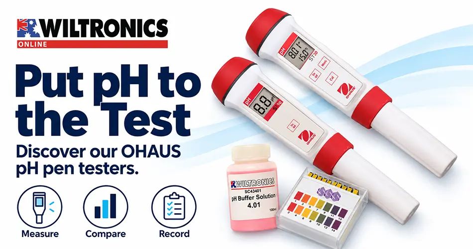
pH Pen Testers: Choosing Between the OHAUS ST10 and ST20 A pH pen tester puts a numerical reading in your hand, making it easier to record and compare liquid samples. Choosing the right pen starts with the measurements you need: straightforward pH checks, or finer readings supported by temperature measurement and user calibration. At Wiltronics, our OHAUS ST10 and ST20 pH pen testers offer two distinct options. This guide compares their features, explains the supporting equipment to consider and outlines a practical way to organise repeatable testing. Quick recommendation: Choose the ST10 for simple pH-only checks where its stated performance suits the task. Choose the ST20 when you need temperature readings, automatic temperature compensation and a user-calibration facility. Compare our OHAUS pH pen testers Feature OHAUS ST10 OHAUS ST20 pH measurement range 0–14 pH 0–14 pH pH resolution 0.1 pH 0.01 pH Stated pH accuracy ±0.1 pH ±0.05 pH Temperature display No Yes Automatic temperature compensation No Yes Calibration Not applicable Three-point Replaceable electrode Yes Yes Housing protection rating IP67 IP67 OHAUS ST10: straightforward pH-only testing Our OHAUS ST10 pH Pen provides a simple starting point when you need pH readings without temperature display or additional measurement functions. Its one-button operation suits a straightforward testing routine. Consider it when a 0.1 pH display increment and the stated accuracy meet your requirements. The important purchasing distinction is calibration: the ST10 listing specifies calibration as not applicable. Do not choose it expecting the ST20’s user-adjustable three-point calibration procedure. A check against a suitable reference solution can help assess performance, but checking a reading is not the same as adjusting the meter. OHAUS ST20: pH, temperature and calibration Our OHAUS ST20 pH & Temperature Pen adds features for a more controlled measurement routine. Its finer pH resolution, temperature display and calibration function make it our stronger option for users who want to record sample conditions and maintain a regular calibration process. In education, it also provides opportunities to teach the difference between checking an instrument, calibrating it and measuring an unknown sample. The listing gives a temperature measurement range of 0–99°C and stated temperature accuracy of ±0.5°C. The instrument’s ambient operating limits are separate from its sample-temperature range; consult the supplied instructions before testing hot or cold liquids. Resolution is not the same as accuracy Resolution is the smallest step shown on the display. Accuracy describes how closely the instrument is specified to measure under stated conditions. For example, a display that changes in 0.01 pH steps does not establish accuracy of ±0.01 pH. Avoid treating every change in the last digit as evidence that the sample has meaningfully changed. Before selecting a tester, write down the decision the reading will support. If you need to distinguish very small differences, compare the required uncertainty with the complete measurement method, not simply the number of decimal places. Build a complete pH testing station Suitable pH buffers Our pH buffer range supports instrument checks and calibration where the meter permits it. Choose buffers compatible with the exact model’s recognised values and procedure. Follow the supplied instructions rather than assuming every pH pen accepts the same calibration sequence. Pour small working portions into clean, labelled containers. Do not return used buffer to the original bottle. Record the buffer identity and expiry information alongside the instrument check or calibration record. Model-specific replacement electrodes Wiltronics supplies the OHAUS Replacement Pen Electrode for ST10—ME4319 and the OHAUS Replacement Electrode for ST20—ME4321. Match the replacement to the pen model. Including electrode maintenance in your equipment plan makes it easier to keep a testing station usable over time. Follow the replacement and preparation procedure before putting a new electrode into service. Containers and sample-transfer accessories Our Low-Form Polypropylene Beakers can help organise separate samples, rinse water and buffer portions. Disposable Transfer Pipettes are useful for transferring small quantities into those containers. Assign separate pipettes to different solutions to reduce carry-over. Provide enough sample for the specified electrode immersion depth. A few drops suitable for indicator paper may not be enough for a pen tester. A practical measurement routine Prepare the electrode as directed before first use or after storage. The OHAUS ST20 instructions specify conditioning in electrode protection solution and maintaining storage solution in the protective cap. Follow the instructions supplied with your exact unit for preparation, cleaning and storage. Identify the sample. Label its container and note preparation details relevant to the comparison. Check instrument readiness. Inspect the electrode and battery status. For the ST20, complete the required calibration routine with suitable buffers. Rinse between solutions. Use the rinse water specified by the manufacturer and handle the fragile sensing element carefully. Immerse correctly. Follow the model’s immersion instructions and allow the reading to stabilise before recording it. Record the conditions. Note the pen model, pH result and temperature when available. Finish with electrode care. Clean and store the electrode as instructed, with the protective cap fitted. IP67 protection does not replace the measurement instructions or permit unrestricted immersion in every liquid. Classroom investigation: compare readings and repeatability Use this suggested activity for an age-appropriate class after teacher review. The reviewed OHAUS ST20 manual states that the pen should not be used by children aged 12 or younger; use a teacher-operated demonstration for those groups and check the instructions supplied with your unit. Prepare three labelled, teacher-approved aqueous samples at similar room temperature. Select samples that suit the electrode and the school’s risk assessment. Students should measure them separately rather than mixing them. Ask students to predict the order from lowest to highest pH. Then record measurements using the procedure above. For a second reading, use a fresh portion of the same prepared sample and repeat the handling steps. Sample Predicted order First pH reading Repeat pH reading Temperature, if measured Notes A B C Discuss whether differences between repeat readings are large enough to matter for the task. Repeated agreement shows repeatability; it does not, by itself, prove accuracy. As an optional comparison, use pH indicator strips on separate sample portions. Ask students why a broad colour estimate and a numerical reading may provide different levels of detail without necessarily contradicting each other. Troubleshooting unexpected readings Observation Useful first checks Reading takes a long time to settle Electrode preparation, cleanliness and sample suitability A reference check is outside expectations Buffer condition, temperature, electrode condition and model-specific calibration options Repeat results differ Carry-over, inconsistent sample preparation or insufficient settling time Two pens disagree slightly Their stated accuracy, calibration status and sample conditions Display is faint or the pen will not start Batteries and the manufacturer’s maintenance instructions If a check fails, investigate before using subsequent readings to make a decision. Repeating an unreliable method can produce a consistent-looking set of results without resolving its underlying problem. Frequently asked questions Which pH pen should I choose for calibration lessons? The ST20 is the appropriate choice between these two models because it provides user calibration. The ST10 listing does not specify a user-calibration function. Does automatic temperature compensation make every sample read the same at different temperatures? No. It compensates for the electrode’s temperature-dependent response; a sample’s own pH can still change with temperature. Keep comparison conditions consistent and record temperature where possible. Can these pens be pushed directly into soil? Do not assume so. These are liquid pH pens. Use a suitable soil-testing method or purpose-designed instrument, and confirm the electrode’s suitability before measuring prepared soil extracts. Can a pH pen establish whether water is safe to drink? No. A pH result alone cannot establish drinking-water safety or identify all contaminants. Are the electrodes replaceable? Yes. Wiltronics lists separate replacement electrodes for the ST10 and ST20. Select the part specified for your model. Choose your pH pen tester with Wiltronics Compare the OHAUS ST10 and OHAUS ST20, or browse our full pH tester range. Choose around the readings you need, then plan for buffers, electrode care and sample handling. That preparation helps turn a convenient handheld instrument into a dependable part of your testing routine.

October 19, 2026
Classroom Density Experiments: How to Measure Mass and Volume Two objects can look the same size yet have noticeably different masses. That simple comparison is a useful starting point for teaching density: students can make a prediction, collect measurements and explain what the numbers show. These classroom density experiments connect balance readings, volume measurements and calculations. Start with regular solids, then introduce water displacement for an irregular object. Along the way, students learn why a convincing answer needs suitable equipment, consistent units and more than a calculator display. Quick answer: Calculate density by dividing mass by volume. Measure a regular block’s volume from its dimensions, or use water displacement for a suitable irregular solid that sinks and can be fully submerged. What is density? Density describes mass per unit volume: Density = mass ÷ volume With mass in grams and volume in cubic centimetres, the answer is in g/cm³. For displacement measurements, 1mL equals 1cm³, so a measured volume in millilitres can be used directly with mass in grams to calculate g/mL. Mass alone does not tell you which material is denser. Comparing equal volumes makes the relationship easier to see: the sample with the greater mass has the greater density. For a rectangular block, volume equals length × width × height. For a cube, this becomes edge length × edge length × edge length. Choose the method before setting up Sample Volume method Main check Regular solid cube or block Measure dimensions and calculate Use the same length unit throughout Irregular solid that sinks Measure the rise in water level Fully submerge it without bubbles or spilled water Floating, absorbent or soluble sample Use a different or adapted method The simple displacement procedure below is unsuitable Prepare a dry weighing area and a separate water station. Each group needs a suitable balance, selected solid samples, a ruler or callipers, a measuring cylinder, water, a tray and a recording sheet. Choose samples approved for the class. Check that they fit freely inside the cylinder and can be lowered and retrieved without forcing them through the opening. Use a thin thread where appropriate, and keep heavy objects under control rather than dropping them into the vessel. Experiment 1: Compare equal-sized cubes Learning goal: explain why equal volumes can have different masses. Choose two or three solid cubes of different materials with matching nominal dimensions. Aluminium, brass and copper provide a useful starting selection. Label the samples A, B and C. Ask students to predict their mass order before weighing. Measure each sample’s length, width and height. Record the units. Convert dimensions to centimetres if calculating volume in cm³. Place the balance on a stable, level surface and follow its setup instructions. Check that it reads zero; tare any weighing container before adding a sample. Weigh each dry cube separately and record its mass in grams. Calculate volume and divide mass by volume. Compare the calculated densities with the original predictions. Sample Length (cm) Width (cm) Height (cm) Volume (cm³) Mass (g) Density (g/cm³) A B C Worked example For an illustrative cube measuring 2.00cm along each edge: Volume = 2.00 × 2.00 × 2.00 = 8.00cm³. If its measured mass is 21.6g, density = 21.6 ÷ 8.00 = 2.70g/cm³. These are example values, not guaranteed readings for a purchased cube. Students should calculate from their own measurements and report precision appropriate to their instruments. Discussion prompt: “If we cut a uniform cube into two pieces, what happens to each piece’s mass, volume and density?” The mass and volume of each piece decrease, but the material’s density remains approximately the same under the same conditions. Experiment 2: Measure an irregular solid by water displacement Learning goal: find a volume that cannot easily be calculated from external dimensions. Use a teacher-selected, non-porous solid that sinks, does not dissolve or react with water, and fits comfortably inside the measuring cylinder. Weigh it while dry before beginning the water measurements. Add enough water to cover the sample when immersed, leaving room below the cylinder’s maximum scale mark. Stand the cylinder on a level surface. Read the initial volume at eye level, using the bottom of a concave water meniscus. Lower the sample gently into the water. Fully submerge it and release any trapped air bubbles. Record the final water level using the same reading method. Subtract the initial reading from the final reading to obtain the displaced volume. Divide the sample’s dry mass by that volume. Example: A 54.0g sample raises the water level from 40.0mL to 60.0mL. Displaced volume = 60.0 − 40.0 = 20.0mL. Density = 54.0 ÷ 20.0 = 2.70g/mL, equivalent to 2.70g/cm³. Use these decimal places only if the cylinder’s scale supports them. A coarse scale cannot justify a finely reported result. For a repeat trial, re-establish and record the starting water level. Do not assume it remains unchanged after removing a wet sample. Equipment to support your density lesson Individual density cubes Wiltronics’ Density Cube range includes aluminium, brass, copper and iron options, alongside other variants. Individual selection lets you assemble a comparison set around your lesson requirements. Choose matching edge sizes for the first investigation. Confirm the selected dimensions before ordering, then have students measure the actual samples during the activity. Edge length is a length measurement; it should not be confused with the cube’s volume. OHAUS Scout SKX622 Educational Balance The OHAUS Scout SKX622 has a capacity of 620g and readability of 0.01g. It offers a way to measure classroom samples in grams, but a balance you already own may also suit the task. Check the total load, including any container, and choose readability appropriate to the samples. Readability describes the display increment; it is not a guarantee of overall measurement accuracy. Students can carry out these investigations using ordinary mass readings and their own calculations. A dedicated density accessory is not required for the methods described here. Polypropylene graduated measuring cylinders Our Polypropylene Graduated Measuring Cylinders range includes capacities from 10mL to 1000mL. Choose a cylinder that accommodates the sample, starting water and displacement while providing useful scale divisions. A smaller cylinder can improve the readability of a small change in volume, but only if the object fits freely and there is enough capacity. For a refresher on scale divisions and reading technique, see How to Measure Liquid Volume: A Practical Classroom Guide. Common errors and what to check Result or problem Practical check Calculated density is unexpectedly high Was the displaced volume underestimated, or a container included in the mass? Calculated density is unexpectedly low Were air bubbles attached to the sample, increasing the apparent volume? Cube volume looks incorrect Were millimetres mixed with centimetres? Were all three dimensions multiplied? Results vary between groups Compare zeroing, scale reading, sample dimensions and water loss Density has many decimal places Round to reflect the quality of the original measurements A cylinder measures displacement using two readings. When the rise in water level is very small, reading uncertainty becomes a large proportion of the calculated volume. Repeating the calculation will not fix an unsuitable measuring setup. Encourage students to retain unexpected measurements, explain possible causes and improve their method. Changing results to match a reference value removes the evidence they need to evaluate the investigation. Quick assessment Ask students to answer three questions: Two solid samples each occupy 10cm³. One has a mass of 25g and the other 80g. Calculate both densities and identify the denser sample. Why must the initial water reading be subtracted from the final reading? Explain one change that would improve your own investigation, using a specific observation from the activity. Teacher check: The densities are 2.5g/cm³ and 8.0g/cm³. The difference between water readings gives the sample’s displaced volume. An improvement should address an observed measurement limitation. Frequently asked questions Can density identify an unknown material? It can help narrow the possibilities, but is not proof on its own. Different materials can have similar densities, and measurement uncertainty, hollow spaces or mixed composition can affect the result. Can I use a beaker for water displacement? A beaker can show that water rises, but its approximate markings are generally less useful for calculating a small displaced volume. Choose a graduated cylinder with suitable divisions for quantitative work. What if the object floats? A floating object is only partly submerged, so the rise in water level does not give its full volume. Use a sinking sample for this introductory activity; a sinker method requires an additional correction. Prepare your next density investigation with Wiltronics Start with density cubes, then match your balance and measuring cylinder to the samples students will investigate. Ask students to predict first, measure carefully and explain their answer with evidence. The most useful outcome is understanding how mass and volume work together to describe a material.

October 16, 2026
Reflection and Refraction Experiments: A Practical Classroom Guide A beam of light changing direction can catch students’ attention. Tracing its path, measuring angles and explaining the result turns that observation into a useful science investigation. Reflection and refraction experiments give students a practical way to connect diagrams with real equipment. They also reveal common mistakes, particularly measuring angles from a surface instead of from the normal. For Term 4 science, this guide offers two introductory ray-tracing activities, Wiltronics equipment highlights and practical troubleshooting advice. Adapt the activities to students’ experience and the instructions for your equipment. Start with one narrow ray, mark the surface carefully and measure angles from the normal. Reflection and refraction: what is the difference? Reflection returns light into the medium it came from. Refraction occurs when light passes between media with different refractive indices; at oblique incidence, this generally changes its direction. For these activities, the normal is a reference line drawn at 90° to the surface where the ray meets it. Feature Reflection activity Refraction activity Main component Plane mirror Transparent rectangular block Path to investigate Incident and reflected rays Incident, internal and emerging rays Key observation Reflection angle equals incidence angle Direction changes at the block’s boundaries Reference for angles Normal to the mirror Normal to the relevant block face A ray entering a transparent block along the normal does not bend away from its original direction. Use an oblique angle when first demonstrating the change in direction. Prepare a clear ray-tracing station For each working group, prepare: A suitable classroom light box or ray box with a single-slit arrangement. The specified compatible power supply. A plane mirror with a stable support. A transparent rectangular optical block. White paper, pencil, ruler and protractor. A recording sheet. Test the setup before the lesson. Check that the ray crosses the paper clearly and strikes the optical component at the correct height. Reduce ambient light enough to see the paths while keeping the workspace usable. Keep bright beams away from eyes and follow the manufacturer’s guidance on lamp heat, ventilation and power connections. These activities use a classroom ray box. A laser is not required. Activity 1: Measure the angle of reflection Learning goal: use measurements to test the relationship between incident and reflected rays. Place the mirror upright on paper and mark the position of its reflecting surface. Direct a single narrow ray towards it at an angle. Mark two separated points along the centre of the incident ray and two along the reflected ray. Switch off the source before removing equipment to complete the drawing. Join the points with a ruler and locate the point of incidence. Draw the normal perpendicular to the mirror at that point. Measure both angles from the normal. Repeat at three or more incident angles. Suitable starting targets might be 20°, 40° and 60°, adjusted to suit the equipment. Trial Angle of incidence Angle of reflection Difference between readings 1 2 3 The law of reflection predicts equal angles. Small differences in students’ readings should prompt discussion of alignment, beam width and marking accuracy. Do not ask students to change their recorded results to match the prediction. Teaching prompt: “What would happen to your measurements if you used the mirror surface as your reference instead?” Activity 2: Trace light through a rectangular block Learning goal: identify the changes in direction at two boundaries. Place the block flat on paper and trace its outline. Aim the ray so it enters one long face obliquely and leaves the opposite parallel face, without reaching a corner. Mark two points along the incoming ray and two along the emerging ray. Keep the block fixed while marking. Switch off the source and remove the block. Extend the marked ray lines to the traced boundaries. Join the entry and exit points to reconstruct the path inside the block. Draw a normal at each boundary. Add arrows showing the direction of travel. The internal ray may not be clearly visible in a clean transparent block. Reconstructing it from the entry and exit points is part of this method. For light travelling from air into ordinary glass or acrylic at an oblique angle, the ray bends towards the normal. On leaving for air, it bends away from the normal. With parallel faces and air on both sides, the emerging ray is parallel to the original incident ray, but is generally displaced sideways. Ask students to distinguish parallel from following the same line. Teaching prompt: “The ray emerges in the same direction. Does that mean it travelled straight through without changing direction?” Turn ray diagrams into evidence Ask each student to submit a diagram containing: The mirror position or block outline. Straight ray lines with direction arrows. A clearly labelled normal at each relevant boundary. Measured angles where requested. A short explanation supported by the drawing. For students ready for an extension, repeat the block investigation at several incident angles. Keep the block and entry face consistent, then compare the emerging paths. Begin with descriptions and diagrams. Introduce calculations such as Snell’s law only when they suit the learning objective. Quick assessment: predict, label and explain Finish with these three prompts: Draw and label the normal where a ray meets a plane mirror. If the incidence angle is 35°, predict the reflection angle and name the law you used. Use one pair of your recorded reflection angles to explain whether your measurements support the prediction. Suggest one source of measurement uncertainty. Sketch a ray entering and leaving opposite parallel faces of a rectangular block in air. Explain how the emerging ray can be parallel to the incident ray without following the same line. Teacher check: Look for a perpendicular normal, a predicted reflection angle of 35°, evidence from actual readings, and a distinction between direction and sideways displacement. Wiltronics equipment for classroom optics IEC Hodson Light Box & Optical Set 12V Our IEC Hodson Light Box & Optical Set—HL2060-001 supports foundational optics and colour investigations. The listing includes mirrors, multiple slit formers, colour filters and plates. Operating instructions and an experimental manual are linked on the product page. Check the kit contents and compatible power requirements when preparing class sets. A 12V light box must use the supply specified for the apparatus; it is not connected directly to mains power. Rectangular Acrylic Prism Our Rectangular Acrylic Prism—125 × 65 × 18mm provides an option for tracing refraction through a rectangular block. Check that the block’s dimensions and the ray height suit your existing source. Position it so the beam enters and exits the intended parallel faces. IEC Light Box Angular Scale for Rays Our IEC Light Box Angular Scale for Rays—PA2060-090 is a 165 × 165mm accessory for measuring ray angles. The listing states that it fits inside the kit housing and is not included in the standard Light Box kit. It offers an alternative to measuring traced rays with a separate protractor. Students still need to identify the normal and use the correct angle reference. Equilateral Triangular Glass Prism Our Equilateral Triangular Glass Prism is available in 38mm and 50mm sizes, with a 60°/60°/60° design. Use it for a later comparison with the rectangular block. Its entry and exit faces are not parallel, so students should not expect the same emerging-ray geometry. For white-light dispersion work, check the source, slit arrangement and screen position before planning the demonstration. Common problems and practical checks Problem What to check Rays are difficult to trace Ambient light, slit selection, focus and beam height Reflection angles appear different Normal placement, mirror alignment and ray-centre markings A faint second reflection appears Whether the mirror’s front glass surface produces an additional reflection Refraction is difficult to observe Whether the incident ray is too close to the normal The emerging ray is not parallel in the block activity Whether it crossed opposite parallel faces and the block stayed in its outline Where a mirror has a reflective coating behind glass, its effective reflecting surface is behind the front face. Use the apparatus instructions to position it correctly and discuss any resulting uncertainty. Frequently asked questions Do we need a laser for these activities? No. Use a suitable classroom ray box with a single-slit arrangement. Why measure angles from the normal? The normal is the standard reference for both laws, allowing measurements to be compared consistently. Does light always bend when entering glass? No. At normal incidence, it continues in the same direction, although its speed changes. Why does light leaving a rectangular block travel parallel to the incoming ray? With air on both sides and parallel entry and exit faces, the two changes in direction cancel. The ray can still be displaced sideways. Can we use a triangular prism instead of the rectangular block? Use it as a separate investigation. Its angled faces change the geometry, so the rectangular-block prediction does not apply. Prepare your next light investigation with Wiltronics Explore our light and optics equipment for light boxes, mirrors, lenses, prisms and related teaching apparatus. Give students time to predict the path, trace what happens and explain the difference. A carefully labelled ray diagram makes their reasoning visible.

October 15, 2026
Using a Spring Balance: Classroom Force Experiments How much force does it take to lift an object or pull it across a desk? A spring balance helps students turn those questions into measurements they can compare and explain. For Term 4 practical work, force investigations offer a useful progression from reading a scale to planning a fair test. Students can explore weight and friction while learning why the instrument’s range and the way it is used matter. At Wiltronics, our spring balances and push/pull dynamometers provide options for classroom force measurements. This guide includes two practical activities, equipment highlights and an extension for students ready to investigate spring behaviour. Choose a suitable range, check zero and record force in newtons. What does a spring balance measure? A spring balance measures force in newtons (N) through the deformation of a spring. This guide focuses on taking useful readings and planning classroom comparisons. Choose the range before the lesson A balance must accommodate the largest expected force, including any brief peak when movement begins. A high-capacity instrument may be difficult to read for small forces. A low-capacity instrument may be overloaded. Compare both the range and the smallest scale division before selecting a class set. For example, a suspended 200g mass has a weight of approximately 1.96N near Earth’s surface. A 1N balance is unsuitable for that load. Check the instrument’s operating instructions and permitted orientation. Keep the force aligned with its measuring axis, and use a model designed for pushing if the activity involves compression. Before students begin: Inspect the hook, attachment and casing. Check zero in the intended working position; adjust only as instructed. Identify the newton scale and the value of each interval. Apply loads gently and remain within the instrument’s range. Activity 1: Compare the weight of classroom objects Learning goal: take a steady force reading and compare it with a prediction. For an object hanging at rest with no other support, the balance reading equals its weight. Mass and weight are different quantities: Quantity Meaning Unit Mass A property of the object associated with its inertia Kilograms (kg), or grams (g) Weight The gravitational force acting on the object Newtons (N) Near Earth’s surface, weight can be calculated using W = mg. A 100g mass is 0.100kg and has a weight of approximately 0.98N when using g = 9.8N/kg. Some classroom scales use the convenient approximation that 100g corresponds to 1N. This is not an exact conversion. Where a spring balance has both gram and newton markings, the gram scale indicates an equivalent mass under its calibration assumptions. For force investigations, ask students to use the newton scale consistently. Choose several small objects that can be securely attached and whose expected weights are comfortably within the balance’s capacity. The teacher should check the complete setup first. Ask students to predict the order from smallest to largest weight. For each object: Attach it securely while supporting it. Transfer the load gently to the balance. Let it hang freely without touching the bench. Wait until movement settles. Read the scale at eye level and record the force in newtons. Keep objects close above a clear bench or suitable tray. Do not suspend loads over people. Object Predicted order Force reading (N) Observation A B C If using an extra carrier or attachment, include its contribution in the measurement or account for it explicitly. Ask students whether their observations support their predictions. For an extension, measure each object’s mass with a suitable balance and compare the spring-balance reading with the calculated weight. Teaching prompt: “Why must the object hang freely when we take the reading?” Activity 2: Compare the force needed to slide an object Learning goal: investigate friction while controlling other variables. Use a suitable force meter, a securely attached block or small container, and two or three flat, secured test surfaces. Pull horizontally along the same straight path. Keep the object, load, contact face and approximate sliding speed consistent. For each surface: Increase the pull gently until the object starts moving. Observe the largest reading just before movement begins, if it can be read reliably. Continue pulling at an approximately steady speed. Record the force during steady sliding. Repeat three times. Surface Trial Peak before movement (N) Steady sliding force (N) A 1 A 2 A 3 B 1 B 2 B 3 A brief starting peak can be difficult to capture with an analogue meter. If students cannot read it reliably, focus the comparison on steady sliding. When the object moves horizontally at constant speed and other horizontal forces are negligible, the pulling force approximately balances sliding friction. If students jerk the object or accelerate it, the reading includes the force associated with that acceleration. Pulling upwards at an angle changes the contact force against the surface, making the comparison less controlled. Ask students to report which surface required the greater pull in their test, supported by repeated readings. Avoid assuming that appearance alone predicts friction. Wiltronics equipment for force investigations Dual-scale spring balances Our Spring Balance range features colour-coded instruments with gram and newton scales. Listed force ranges extend from 1N to 50N. Select the range for the expected load and check the scale divisions before preparing the activity. Different ranges are useful for different tasks, rather than being interchangeable. Economy spring balances Our Spring Balance Economy range offers dual-scale options from 1N to 20N. The product listing notes that brand and appearance can vary with supplier availability. When preparing shared instructions, check the markings and controls on the actual instruments students will receive. Push/pull dynamometers Our Push/Pull Dynamometers provide options for investigating both pushing and pulling forces. Listed ranges run from 2.5N to 50N. These are useful when the teaching task requires more than a hanging-load measurement. Follow the model’s instructions for each loading direction and select a suitable capacity. Hooke’s law spring set Our Hooke’s Law Spring Set of 5 provides an option for extending the lesson from reading force to investigating spring extension. These experimental springs are separate from a calibrated spring balance. Plan the required support, ruler and loads, and confirm the permitted loading conditions before use. Extension: investigate force and spring extension Use a suitable experimental spring, stable support and teacher-approved loads to compare applied force with extension: Extension = loaded length − unloaded length. Students can plot force against extension and identify the region where they are proportional. Stay within the supplier’s permitted loading conditions; do not deliberately overload the spring. Follow the equipment instructions and your school’s procedures. Common problems and what to check Problem Practical check The reading is not zero before loading Working orientation and permitted zero adjustment The pointer moves continuously Swinging load or uneven pulling Groups obtain different friction readings Pull angle, speed, load and surface condition The object still rests partly on the desk Another support is carrying some of its weight Small differences cannot be resolved Instrument range and scale spacing The instrument does not return to zero Remove it from use for inspection Frequently asked questions Should students record grams or newtons? Use newtons when reporting force. Gram markings are an equivalent-mass scale, not a second unit of force. Can every spring balance measure a pushing force? No. Use an instrument designed for push measurements and follow its operating instructions. Why can it take more force to start an object moving? The maximum static friction before sliding often exceeds the friction during sliding. Check that any observed peak is not caused by a sudden jerk. Is the largest-range balance the best choice? Not automatically. It must handle the load, but its scale must also allow students to distinguish the forces being compared. Do students need to study Hooke’s law first? No. Begin with steady readings and comparisons. Introduce the spring’s force–extension relationship when students are ready to measure and graph it. Bring force investigations into your classroom Explore our spring balances and motion, force and density equipment to prepare your next practical lesson. Start with a measurable question, choose equipment that suits the expected force and help students explain how their method affects the result.

October 13, 2026
How to Measure Liquid Volume: A Practical Classroom Guide Two groups can follow the same experiment and get different results because they measured their liquids differently. A reading taken from above, a misunderstood scale or an unsuitable vessel can introduce differences before the investigation begins. For Term 4 science, a short lesson on measuring liquid volume helps students develop habits they can use in later chemistry and biology practicals. At Wiltronics, our measuring cylinders and pipettes support activities ranging from introductory scale reading to more demanding liquid transfers. This guide combines equipment choices with two water-based classroom activities, practical checks and common questions. Start with the scale, read at eye level and record what the instrument can reasonably show. Choose the instrument for the task A vessel’s capacity tells you how much it holds. It does not, by itself, tell you how accurately it measures. Task Useful starting point What to check Hold or mix water for an activity Beaker Capacity and material suitability Measure a variable volume Graduated measuring cylinder Range, scale divisions and stated tolerance Add water gradually near a target mark Transfer pipette Controlled dispensing Transfer a specified fixed volume Volumetric pipette with a suitable filler Nominal volume, tolerance and delivery instructions Beaker markings generally provide approximate volumes. Use a suitable measuring instrument when volume affects the result. A transfer pipette used for adding drops should not automatically be treated as a calibrated measuring pipette. For material selection, see our Glass vs Plastic Labware guide. Read the scale before adding water Ask students to identify the unit, maximum marked volume and value of each interval. For example, if five equal intervals separate the 10mL and 20mL marks: (20 − 10) ÷ 5 = 2mL per interval. Count the spaces between marks, not just the lines. This is a worked example, not a specification for every cylinder. Check the actual instrument students will use. Choose a capacity that accommodates the target volume while providing useful scale divisions. A large cylinder may hold the required amount but make a small volume difficult to read. Distinguish the smallest scale division from the manufacturer’s tolerance. Closely spaced marks do not, on their own, establish accuracy. How to read the meniscus The meniscus is the curved liquid surface. For water forming a concave meniscus, read the bottom of the curve. Place the cylinder upright on a level surface. Allow the liquid to settle. Bring your eyes level with the meniscus. Read the scale at the lowest part of the curve. Record the volume and unit. Looking from above or below creates parallax: the liquid level appears to align with a different point on the scale. Use this method for the water activities below. Other liquids and instruments may require different reading procedures. Activity 1: Does viewing angle change the reading? Learning goal: recognise parallax without changing the liquid volume. Prepare a cylinder of water with the meniscus between labelled marks. Keep the cylinder in one position. Ask students to take readings from slightly above, at eye level and slightly below the meniscus. Viewing position Volume reading (mL) Above the meniscus Level with the meniscus Below the meniscus Students should compare readings before discussing the correct technique. Ask: Did the amount of water change? What changed between observations? Which reading follows the agreed method? If the differences are too small to distinguish on your equipment, discuss that limitation instead of expecting a particular numerical result. Teaching prompt: “Could two people report different volumes without either adding or removing water?” Activity 2: Practise filling and reading a target volume Learning goal: practise controlled filling and compare readings of the same liquid level. Give each group water, a suitable cylinder, a transfer pipette and a collection beaker. Select a target suited to the cylinder’s capacity and graduations. One student fills to just below the target, then adds water gradually. A second student checks the reading at eye level without first being told the first student’s result. Record both readings before discussing any difference. Empty the cylinder and repeat using the same preparation method, swapping roles. Attempt Target (mL) First reading (mL) Independent reading (mL) Technique note 1 2 3 This activity checks handling and agreement between readers. It does not independently verify accuracy: two students may share the same error. Evaluating accuracy requires an appropriate reference or validated method. Explain accuracy and precision separately For classroom discussion: Accuracy concerns how close a measurement is to the true or accepted reference value. Precision concerns how closely repeated measurements agree under stated conditions. Ask students to identify one change that could improve their technique, such as using a more suitable scale or keeping their viewing position consistent. When recording results, follow the class convention for estimating between graduations. Avoid adding decimal places that the scale and observation cannot support. Wiltronics equipment for liquid-volume lessons Polypropylene measuring cylinders Our Graduated Measuring Cylinders—Polypropylene have pouring spouts and bases, with listed capacities from 10mL to 1000mL. Compare the available sizes against the volumes students will measure. Confirm graduations and tolerance where these are important to the investigation. Borosilicate glass measuring cylinders Our Graduated Measuring Cylinders—Borosilicate Glass with Hex Base are available in listed capacities from 10mL to 2000mL. They provide another material option for laboratory work. Select equipment according to the activity and handling requirements; glass construction alone is not an accuracy specification. Disposable transfer pipettes Our Disposable Pipettes—Pack of 100 provide options for liquid transfer. For the target-volume activity, use a suitable pipette to approach the mark gradually. Read the final volume from the cylinder rather than assuming a fixed volume per drop. Class A volumetric pipettes For an extension involving a fixed-volume transfer, our Class A Volumetric Pipettes have a single graduation mark and listed tolerances. The 10mL option has a listed tolerance of ±0.020mL. This is an instrument specification, not a guarantee of the total uncertainty in a student’s result. Use a suitable pipette filler, never mouth pipetting, and follow the instrument’s delivery instructions. Do not assume every pipette should have its remaining liquid blown out. Common mistakes and practical checks Problem What to check Different students read the same cylinder differently Eye position and the chosen point on the meniscus Results are consistently too high or low Scale interpretation and repeated technique errors Students overshoot the target Add smaller amounts as the liquid approaches the mark A small volume is difficult to judge Cylinder capacity and graduation spacing Too many decimal places appear in results Whether the scale supports the recorded detail Less liquid arrives in the receiving vessel than expected Spills, retained liquid and whether the instrument is calibrated to contain or deliver Follow your school’s procedures for spills and glass handling. The introductory activities use water; other liquids require their own suitability checks. Frequently asked questions Is a measuring cylinder more suitable than a beaker for measuring volume? Usually. Beaker markings are generally approximate; select a cylinder with specifications suited to the task. Should students always read the bottom of the meniscus? Yes for water with a concave meniscus. Follow the specified method for other liquids and instruments. Does a smaller graduation mean a smaller tolerance? No. Scale divisions describe the markings; tolerance describes the permitted volume error under specified conditions. Do matching readings prove that the volume is correct? No. Agreement alone does not establish accuracy. Can students measure volume by counting drops? Only with an established drop volume for the liquid and dispensing conditions. Otherwise, read the volume with a suitable measuring instrument. Build better measurement habits with Wiltronics Explore our measuring cylinders and pipettes to prepare your next practical lesson. Help students explain their equipment choice, demonstrate a consistent reading method and recognise the limits of their results. Those habits remain useful long after the first water-measuring activity.

October 12, 2026
Classroom Microscope Activities: Observe, Compare and Draw Finding a specimen is only the beginning of a microscope lesson. The next step is helping students describe what they can see, compare structures and support their explanations with evidence. For Term 4 practical work, a short sequence of microscope activities can build these skills without introducing slide preparation at the same time. At Wiltronics, our prepared slides, microscope accessories and storage options help teachers organise lessons around observation. This guide starts with finding and focusing a specimen, then develops comparison and recording tasks. Begin with one clearly visible specimen. Build confidence before increasing magnification or adding more complex identification tasks. Choose the learning goal Choose the outcome before selecting the slides. Learning goal Suggested task Evidence students produce Develop focusing skills Locate a teacher-selected specimen A focused view checked by the teacher Describe visible features Observe one selected area Three precise observations Compare structures Examine two prepared specimens A comparison table Record evidence Draw a selected field or structure A labelled observational drawing These are adaptable teaching ideas, not a prescribed sequence for every year level. Preview the specimens with your classroom microscopes and set expectations appropriate to students’ experience. For help choosing an instrument, see our School Microscope Buying Guide. The activities below focus on prepared slides viewed with a compound biological microscope. Select your specimens Prepare a suitable microscope, selected slides and a recording sheet for each station. Our Prepared Botany Microscope Slides—Set of 25 includes monocot and dicot stem sections, leaf and root sections, Spirogyra and other preparations. For broader comparisons, our Prepared Biology Microscope Slides—Set of 25 includes Spirogyra, onion root tips and several tissue preparations. Review the full contents before choosing specimens for your class. Plan a slide rotation or provide duplicates for simultaneous observations. Give every student time at the eyepiece. Activity 1: Find, focus and describe Beginner focus: locating a specimen and describing visible features. Start with a prepared slide you have already checked for clear, readily located features. Demonstrate the controls on the actual microscope students will use. Begin with the lowest-power objective, position the specimen over the illumination and follow the instrument’s focusing instructions. Once students find the specimen, ask them to centre an area of interest. When moving to higher-power objectives, use fine focus and maintain clearance between the objective and slide. If the specimen is lost, return to low power and locate it again. Ask students to record three observations before naming structures. Useful prompts include: What shapes or repeating patterns can you see? How are the visible structures arranged? Which boundaries are clear, and which remain uncertain? “I can see repeated compartments arranged in rows” gives the discussion a firmer starting point than an unsupported label. Teaching prompt: “What can you point to in the specimen that supports your description?” Activity 2: Compare two plant sections Guided extension: comparing tissue arrangements for students with some background in plant structure. Use the monocot and dicot stem cross-sections from the botany set. Preview both slides and provide a reference appropriate to the students’ prior knowledge. Begin by asking students to describe the overall arrangement in each section. Introduce the relevant biological names after students have identified visible differences. Observation question Specimen A Specimen B What is the overall shape of the section? Which patterns or groups of structures stand out? How are those groups arranged? What is one similarity? What is one difference? Use the same microscope settings where practical and record the magnification for each observation. Avoid treating apparent size differences as measurements unless students have a calibrated method. For students not yet ready for tissue identification, simplify the task to describing visible shapes and patterns. Students can also move directly from the focusing activity to drawing the same specimen. Activity 3: Turn observations into a scientific drawing Ask students to draw a selected area from their own microscope view. For this activity, require: A specimen title. Clear outlines showing the observed arrangement. Labels for features they can identify confidently. The total viewing magnification. One sentence explaining a visible feature. For a conventional compound microscope, total viewing magnification is the eyepiece magnification multiplied by the objective magnification. A 10× eyepiece with a 10× objective gives 100× total magnification. Record this as the viewing magnification; it does not establish the scale of the drawing. Encourage students to leave an uncertain feature unlabelled and ask about it. Their drawing should record evidence from the slide rather than reproduce a remembered textbook image. Extend to slide preparation when students are ready Once students can locate, focus and record a prepared specimen, a separate lesson can introduce making slides using a teacher-approved method. Our Premium Glass Microscope Slides—Pack of 50 includes standard, concave and frosted-end options. Select the format specified by your activity. Our Glass Microscope Coverslips come in boxes of 100, with 18mm and 22mm square options. Check the required size and suitability for the microscope and specimen. Calculate consumables separately from reusable equipment. Ten stations preparing two new slides each require 20 slides, before allowing for repeat attempts or breakage. Follow your school’s procedures for glass handling, specimen preparation and any stains used. Troubleshoot before changing the specimen Problem First checks No useful image appears Illumination, objective engagement and specimen position The specimen disappears at higher power Return to low power, find it and centre the area of interest The image remains unclear Fine focus, slide orientation and cleanliness Students report different features Whether they are viewing the same region at the same magnification A student cannot explain a label Ask them to point out the feature and describe the evidence Use lens-cleaning materials and methods recommended by the microscope manufacturer. Avoid wiping optical surfaces with clothing or paper towel. Check understanding before packing away Ask each student for one observation supported by their drawing and one question they would investigate next. Students completing the comparison activity should also explain one difference between the specimens. Keep slides organised in their cases or our Microscope Slide Boxes, available in 25-, 50- and 100-slide capacities. Frequently asked questions Are prepared slides useful for beginner microscope lessons? Yes. They let students practise observation and focusing before taking on specimen preparation. Choose slides you have previewed and can use to demonstrate clear features. Should students begin at the highest magnification? No. Begin with the lowest-power objective to locate and centre the specimen, then increase magnification when the task requires it. Can one slide set support a whole class? It can support a planned rotation. Check how many copies of each specimen are available if groups need to perform the same observation simultaneously. Do we need blank slides and coverslips for these activities? The first three activities use prepared slides. Blank slides and coverslips become relevant when students begin preparing their own specimens. What should students do when they cannot identify a structure? Describe and draw what is visible, then compare it with an appropriate reference or ask the teacher. An uncertain identification is a useful discussion point. Prepare your next microscopy lesson with Wiltronics Explore our microscopes and accessories and microscope slides and equipment to prepare your classroom stations. Start with a focused question, choose specimens that support it and give students time to observe, compare and explain.

October 9, 2026
Teaching Static Electricity: Hands-On Experiments for School Science Static electricity is one of those science topics students can see, hear and sometimes even feel. A charged rod can attract small pieces of paper. Two objects can repel one another without touching. An electroscope can make an invisible electrical charge visible. And a Van de Graaff generator can turn an abstract physics concept into one of the most memorable demonstrations in the science classroom. But the best electrostatics lessons go beyond producing a spark. Students should have opportunities to predict, observe, compare and explain what happens when electrical charge is generated, transferred and redistributed. At Wiltronics, we supply electrostatics and physics equipment for Australian schools, laboratories and STEM programs. In this guide, we explore six practical ways to teach static electricity, from simple introductory investigations to more advanced classroom demonstrations. What Is Static Electricity? Static electricity is an imbalance of electric charge on or within a material. Atoms contain positively charged protons and negatively charged electrons. When certain materials come into contact and are separated, electrons can transfer between their surfaces. One material may gain electrons while another loses them. This creates an imbalance of charge. Students can then investigate several important ideas: unlike charges attract like charges repel charged objects can attract some neutral objects charge can be transferred between materials charge can move through conductive materials electric forces can act without objects touching Unlike current electricity, where charge continuously moves through a circuit, static electricity generally involves charge accumulating before eventually being transferred or discharged. 1. The Classic Charged Rod Experiment Best for: Introducing electrostatic attraction and charging by friction. Equipment: electrostatic rod suitable rubbing material such as fur, cotton or wool small pieces of lightweight paper What to do: Place several tiny pieces of paper on the bench. Bring an uncharged rod close to them and observe what happens. Next, rub the rod with an appropriate cloth and bring it close to the paper again without touching it. Students should see the lightweight pieces move towards the charged rod. Ask students: What changed after the rod was rubbed? Does the rod need to touch the paper? What evidence suggests an electrical force is acting? What happens as the charge gradually dissipates? This simple experiment introduces an important idea: electrostatic forces can act at a distance. Students can repeat the investigation using different rod materials and rubbing materials. Wiltronics supplies Electrostatic Rods in nylon, acrylic, polystyrene, polyethylene, glass and ebonite, giving students an easy way to compare the electrostatic behaviour of different materials. A dedicated Electrostatic Cloth Set with cotton and wool is also available for classroom electrostatics experiments. 2. Compare Different Materials Once students can successfully create a static charge, the investigation can become more systematic. Equipment: several different electrostatic rods fur, cotton, wool, silk or other suitable rubbing materials small pieces of paper or another simple charge indicator Investigation: Charge each rod using the same number of strokes and compare its apparent ability to attract lightweight objects. Students could create a results table such as: Rod material Rubbing material Attraction observed Relative effect Acrylic Cloth Ebonite Cloth Glass Cloth Polythene Cloth This turns a demonstration into an investigation. Instead of simply showing students that static electricity exists, they can ask: Do different combinations of materials produce the same electrostatic effect? The Wiltronics Electrostatic Kit – LQ1802 is particularly useful for introductory activities because it combines acrylic, plastic and rubber rods with fur and silk for static-friction experiments. Teaching opportunity This is also a good point to discuss why experimental conditions need to remain consistent. Students should try to control variables such as: number of rubbing strokes length of time the rod is rubbed area of material used distance between the rod and test object environmental conditions The experiment may not produce perfectly quantitative results, but it provides an excellent introduction to fair testing. 3. Detect Charge With an Electroscope Attraction of paper makes static electricity visible, but an electroscope allows students to investigate charge more systematically. An electroscope responds when electrical charge is transferred to or induced within its conductive components. Equipment: metal-vane electroscope electrostatic rod suitable rubbing material Investigation: Start with the electroscope discharged. Charge an electrostatic rod and slowly bring it towards the electroscope terminal. Students should observe the response of the vane. Try moving the charged rod closer and further away. Then compare the response produced by differently charged rods. Questions to investigate: Does the rod need to touch the electroscope? How does distance affect the response? What happens when the rod is removed? What happens when charge is transferred directly? Can different materials produce different responses? The IEC Metal Vane Electroscope – EM1810-001 available from Wiltronics is designed to provide a robust and sensitive method of detecting electrostatic charge in classroom investigations. Its metal vane deflects when charge is deposited on the electrode disc, allowing students to observe and compare electrostatic effects. Extend the experiment Ask students to predict what will happen before every change. Prediction → observation → explanation is a powerful structure for practical physics because it exposes the difference between what students expect and what actually happens. 4. Investigate Attraction and Repulsion With Pith Balls A suspended lightweight object can make electrostatic forces particularly easy to observe. Conductive pith balls can be used to demonstrate both attraction and repulsion. Equipment: conductive pith balls insulating thread suitable support charged electrostatic rod or other suitable charge source Wiltronics supplies Electrostatic Conductive Pith Balls – Pack of 10, EM1775-001 for this type of classroom investigation. Investigation: Suspend the pith balls so they hang close together. Introduce a charged object and observe their movement. Different configurations allow students to investigate what happens when charge is transferred and when both suspended objects acquire similar charges. Key idea This provides a visible demonstration of one of electrostatics' most important relationships: like charges repel and opposite charges attract. It is also a useful transition from the familiar idea of charged objects attracting neutral materials to the more sophisticated idea of interactions between charged objects. For a more comprehensive set of experiments, the IEC Electrostatics Kit Nuffield – EM1771-001 includes a metal-vane electroscope, proof plane, electrophorus, conductive pith balls, nylon filament, aluminium cans, insulating tiles, strips and other apparatus. 5. Explore Electrostatic Induction One of the more interesting steps in teaching electrostatics is showing students that an object does not necessarily need to be touched by a charged object for its charges to redistribute. This is electrostatic induction. Equipment: Depending on the demonstration, useful equipment may include: electrostatic rods electroscope insulated conductors metal containers or conductors proof plane or related electrostatic accessories The IEC Electrostatics Kit Nuffield – EM1771-001 provides many of these components in a single classroom kit. Demonstration: Bring a charged object close to an isolated conductor without touching it. The external charge can cause mobile charges within the conductor to redistribute. Students can then investigate how the effect changes when: the charged object moves closer the charged object moves away the conductor is earthed charge is transferred multiple conductors are used Why this matters Induction challenges a common student assumption that electrical effects require direct contact. It also provides an important conceptual bridge towards later study of: electric fields conductors and insulators charge distribution earthing electrostatic shielding For advanced secondary classes, students can begin relating these observations to the behaviour of electrons within conductive materials. 6. Demonstrate High-Voltage Electrostatics With a Van de Graaff Generator Few pieces of physics apparatus create the same immediate reaction from a class as a Van de Graaff generator. A Van de Graaff generator accumulates electrostatic charge on a large conductive dome, allowing high-voltage electrostatic effects to be demonstrated clearly. It can be used to investigate concepts including: charge accumulation electrostatic attraction and repulsion discharge electric fields conductors insulation earthing Demonstrations can include: Electrostatic discharge Position the appropriate earthed discharge sphere near the dome and observe the spark crossing the air gap. Lightweight materials Suitable lightweight materials placed near or on the apparatus can visibly respond as charge accumulates. Charge and distance Students can observe how changing the distance between appropriately configured electrodes affects discharge behaviour. Van de Graaff accessories Purpose-designed accessories can extend the generator into additional demonstrations involving electrostatic forces and charge distribution. Wiltronics supplies several IEC options, including the Large Van de Graaff Generator – 300 mm Ball, EM4133-101 and the compact Small Hand-Operated Van de Graaff Generator – 180 mm Ball, EM4152-001. The hand-operated model is particularly useful where teachers want a manually driven demonstration unit that does not require electrical power. Wiltronics also stocks the IEC Van de Graaff Accessory Set – EM4144-001 for extending the range of demonstrations that can be performed. Important Van de Graaff Safety A Van de Graaff generator is specialised high-voltage demonstration equipment and should not be treated like the simple rod experiments earlier in this guide. Teachers should always follow: the manufacturer's operating instructions the school's laboratory procedures appropriate supervision requirements applicable risk assessments correct earthing and discharge procedures Keep sensitive electronic equipment away from electrostatic demonstrations where recommended by the manufacturer. Anyone with implanted or body-worn electronic medical equipment should not participate in or approach a Van de Graaff demonstration contrary to the manufacturer's safety instructions. The dome should also be correctly discharged according to the equipment instructions before it is handled after operation. A dramatic demonstration is never more important than correct operating procedure. Why Does Static Electricity Sometimes Work Better Than Other Times? Teachers may notice that an electrostatics demonstration works spectacularly one day and barely works the next. Humidity can be a major factor. Moisture on surfaces and in the surrounding air can allow accumulated charge to leak away more quickly. Electrostatic equipment also works best when insulating surfaces are: clean dry free from excessive dust handled appropriately If a normally reliable electrostatic experiment suddenly becomes ineffective, checking environmental conditions and ensuring the apparatus is clean and dry is a sensible first troubleshooting step. Turning a Demonstration Into an Investigation Static electricity is naturally entertaining, but the educational value increases when students do more than watch. Instead of: “Look what happens when I charge this rod.” Try: “Predict what will happen when I bring this charged rod towards the electroscope. What evidence would support your prediction?” Students can investigate variables such as: material type rubbing material charging time distance surface condition humidity conductor versus insulator method of charge transfer They can then record their observations and identify patterns. This transforms a memorable demonstration into genuine scientific inquiry. A Simple Static Electricity Lesson Sequence Teachers introducing electrostatics could progressively build the topic across several activities. Step 1 — Generate charge Use electrostatic rods and a suitable rubbing material to demonstrate attraction of lightweight material. Step 2 — Compare materials Test different rod and rubbing-material combinations using the Electrostatic Kit – LQ1802 or individual rod materials. Step 3 — Detect charge Introduce the IEC Metal Vane Electroscope – EM1810-001. Step 4 — Investigate forces Use conductive pith balls to explore attraction and repulsion. Step 5 — Introduce induction Use the IEC Electrostatics Kit Nuffield – EM1771-001 to investigate charge transfer, induction and charge distribution. Step 6 — Demonstrate larger effects Use an appropriate IEC Van de Graaff generator as a teacher-controlled demonstration to bring the concepts together. This sequence moves students from a phenomenon they can immediately observe towards progressively more sophisticated explanations. Choosing Electrostatics Equipment for Your Science Lab The equipment required depends on the depth of the lesson. For introductory classes Start with: Electrostatic Rods – 300 × 10 mm Electrostatic Cloth Set – Cotton and Wool Electrostatic Kit – LQ1802 These are reusable and well suited to small-group investigations. For more structured investigations Add: IEC Metal Vane Electroscope – EM1810-001 Electrostatic Conductive Pith Balls – EM1775-001 IEC Electrostatics Kit Nuffield – EM1771-001 These allow students to explore attraction, repulsion, charge transfer and induction in greater depth. For whole-class demonstrations Consider: Large IEC Van de Graaff Generator – 300 mm Ball Small Hand-Operated IEC Van de Graaff Generator – 180 mm Ball IEC Van de Graaff Accessory Set – EM4144-001 These can make electrostatic phenomena visible to an entire class and support more advanced physics demonstrations. Frequently Asked Questions What causes static electricity? Static electricity occurs when there is an imbalance of electrical charge. Contact and separation between certain materials can transfer electrons from one surface to another, leaving the objects with different net charges. What is the easiest static electricity experiment for students? One of the simplest experiments is to rub an electrostatic rod with a suitable material and bring it close to small pieces of lightweight paper. The attraction provides an immediate visible indication that the rod has become electrically charged. Why does a charged rod attract neutral paper? A nearby charged object can cause charges within a neutral object to redistribute slightly. The side closest to the charged object can experience a stronger attractive force than the repulsive force acting on charges farther away, producing an overall attraction. What does an electroscope do? An electroscope detects the presence of electric charge. In the IEC Metal Vane Electroscope, electrical charge causes the sensitive metal vane to deflect, giving students a visible indication of electrostatic effects. Why does static electricity work better in dry weather? Moisture provides pathways that allow electrical charge to dissipate from surfaces. Under drier conditions, charge can often remain accumulated for longer, making electrostatic effects easier to observe. What is the difference between static electricity and current electricity? Static electricity involves an accumulation or imbalance of charge. Current electricity involves the continuous movement of electric charge through a conductive path or circuit. What is a Van de Graaff generator used for in schools? A Van de Graaff generator produces and accumulates electrostatic charge so that teachers can demonstrate high-voltage electrostatic effects including attraction, repulsion, charge distribution and electrical discharge. Is a Van de Graaff generator safe for classroom use? It is specialised high-voltage laboratory equipment and should only be operated according to the manufacturer's instructions, school procedures, appropriate supervision and applicable risk assessments. Correct earthing and discharge procedures are essential. What equipment does a school need to teach static electricity? For introductory lessons, electrostatic rods and suitable rubbing materials can be sufficient. An electroscope and electrostatics kit allow more detailed investigations, while a Van de Graaff generator is useful for teacher-led whole-class demonstrations. Where can Australian schools buy electrostatics equipment? Wiltronics supplies electrostatic rods, kits, electroscopes, Van de Graaff generators, accessories and related physics apparatus for Australian schools, laboratories and STEM programs. Browse Electrostatics Equipment at Wiltronics Make Static Electricity Visible Static electricity introduces students to electrical forces in a way that is immediate, surprising and memorable. But the spark is only the starting point. By allowing students to generate charge, compare materials, detect electrostatic effects, investigate attraction and repulsion and explore induction, teachers can turn an invisible physical phenomenon into something students can test for themselves. With the right apparatus and a carefully structured sequence of experiments, electrostatics becomes an excellent platform for developing both physics understanding and practical scientific thinking. Explore Electrostatics Equipment at Wiltronics

October 6, 2026
Teaching Series and Parallel Circuits: A Practical Classroom Guide A lamp lighting up is a useful starting point for an electricity lesson. The deeper learning begins when students can explain why it lights, predict what will happen when the circuit changes and test their predictions. Series and parallel investigations connect circuit diagrams with working equipment. They also reveal common misconceptions, such as the idea that the first lamp “uses up” the current. At Wiltronics, our electricity equipment range includes teaching kits, lamp holders and replacement components for practical circuit work. This guide provides an introductory activity sequence, with optional measurement tasks for students ready to investigate voltage and current. Start with one working lamp circuit, compare two identical lamps in series and parallel, then use observations and measurements to explain the differences. Adapt the activities to your students’ prior knowledge, equipment instructions and school procedures. 1. Establish the difference before building Students need to identify electrical connections rather than memorise the appearance of a drawing. Feature Series circuit Parallel circuit Arrangement Components share one path Components occupy separate branches between common connection points Current The same current passes through each component Current divides between branches Voltage Component voltage drops add to the supply voltage Each branch has the same voltage across it Opening the circuit A break stops current around the single path A break in one branch can leave other branches operating For parallel circuits, distinguish between opening one branch and disconnecting a shared supply connection. A break in the shared connection can stop every branch. These relationships provide the basis for students’ predictions and measurements. www.physicsclassroom.com 2. Prepare a consistent equipment set For an introductory two-lamp investigation, each group needs: A suitable low-voltage DC source. Two filament lamps with matching voltage and current or power ratings. Compatible lamp holders. Enough leads and suitable junction connections for both arrangements. A switch, if included in the planned circuit. Circuit diagrams and a recording sheet. Suitable meters for the optional measurement extension. Choose the supply voltage to suit a single lamp, because each lamp in the parallel arrangement receives the voltage across the supply. Two lamps with the same fitting are not necessarily electrically identical. Check their ratings before distributing them. We recommend testing the complete setup before the lesson. Confirm that the source can supply the combined current required by the parallel branches and that students can identify each connection clearly. Use the equipment according to its instructions and your school’s procedures. Disconnect power before rewiring, avoid short circuits and remember that filament lamps can become hot. 3. Activity one: establish a working baseline Ask students to build a circuit containing the source, one lamp and, where used, a switch. Before switching on, have them trace the complete path from one source terminal, through the lamp and back to the other terminal. Students should record: A circuit diagram. Whether the lamp lights. The effect of opening the switch. An explanation of why a complete path is needed. If the lamp does not light, resolve the fault before adding components. A working baseline makes later comparisons more useful. Teaching prompt: “Which connections must remain in place for current to pass through the lamp?” 4. Activity two: add a second lamp in series Disconnect the supply and add a second identical lamp in the same path. Keep the supply setting unchanged. Ask students to predict: Will both lamps light? Will they have similar brightness? How will their brightness compare with the single-lamp circuit? What will happen if the path is opened at either lamp? With the same supply voltage, two identical filament lamps in series will generally be dimmer than a single lamp. Both carry the same current; the first lamp does not consume current before it reaches the second. Have students compare observations with predictions and explain any differences. Avoid asking for an exact brightness fraction. Filament resistance changes with temperature, so a lamp is not a fixed-resistance component. 5. Activity three: build two parallel branches Disconnect power and rearrange the circuit so each lamp has its own branch across the same two supply connection points. Ask students to trace each complete path separately. Two lamps positioned beside each other are only electrically parallel if their connections form the required branches. Then ask students to predict: How will brightness compare with the single-lamp baseline? What will happen when one branch is opened? Will the source supply more or less total current? With a source that maintains its voltage, each parallel lamp should operate approximately as it did alone. Total supply current increases because the source supplies both branches. Battery voltage drop or a supply reaching its current limit can affect the practical result. If using a switch to control one lamp independently, place it within that lamp’s branch. A switch in the shared supply path controls both branches. Teaching prompt: “When one branch is opened, can you still trace a complete path through the other lamp?” 6. Turn observations into evidence Use a recording table throughout the sequence. Circuit Prediction Observation Explanation using circuit paths One lamp Two lamps in series Series circuit with one break Two lamps in parallel Parallel circuit with one branch open Keep the lamps and supply conditions consistent so students can explain the effect of changing the connections. For students ready to measure, extend the investigation with voltage and current readings: Connect a voltmeter across the component being measured. Connect an ammeter in series with the path whose current is being measured. Check the meter sockets, function and range before applying power. Never connect a meter set to measure current directly across the source. Useful comparisons include current at different positions in a series circuit and total current versus branch currents in a parallel circuit. Treat differences between readings as something to investigate. Connections, source behaviour and measurement limitations can influence the results. 7. Wiltronics equipment highlights IEC Standard Electricity Kit: support a broader electricity program Our IEC Standard Electricity Kit in Aluminium Case—EM1763-001 includes housed components with 4mm banana connections, a 5A power supply, three digital meters, cables and an experiment book. It supports a broader range of DC and AC investigations, making it worth considering when introductory circuit lessons form part of a longer electricity program. Follow its experiment instructions when selecting components and settings. The supply’s maximum current capability is not a recommended current for every activity. IEC Circuits Kit: a compact starting point Our IEC Circuits Kit—EM0970-001 contains two small lamps with sockets, two dry cells, four Fahnstock clips and a selection of copper and resistance wires. It provides apparatus for basic electrical investigations. Check the instructions and connections required for your selected activity before preparing group sets. This differs from the Standard Electricity Kit. Compare the contents with your teaching requirements rather than treating the two kits as interchangeable. MES Lampholder with PVC Base: build reusable stations Our MES Lampholder with PVC Base—LA5100 accepts Miniature Edison Screw lamps. It uses screw connections for wires, requires no soldering and can be screwed to a base plate. For teachers assembling individual stations, it provides a way to secure lamps while keeping their connections accessible. Match the lamp ratings and supply separately; the holder fitting alone does not establish electrical suitability. IEC replacement lamps: keep voltage ratings separate Our IEC Electricity Kit Lamps—PA1763-150 contains ten 2.5V and ten 12V MES lamps in a screw-top vial. The pack provides replacements for compatible apparatus, but it contains two different voltage ratings. Identify and sort the lamps before preparing a lesson. For brightness comparisons, select matching lamps and a suitable source. Mixing the two voltage types introduces another variable into the investigation. IEC spare parts: complete existing teaching sets Our IEC Electricity Kit spare parts range supports schools maintaining existing equipment. Check the kit model and required component before purchasing. Replacing a missing holder or damaged part may restore an otherwise usable teaching set without replacing the whole kit. 8. Common mistakes and practical checks Disconnect power before inspecting or changing connections. Problem What to check Neither lamp lights Source, switch position, complete paths and secure contacts Only one intended parallel branch works Connections and lamp condition in that branch Lamps behave differently Matching ratings, contacts and actual circuit arrangement Lamps dim when a parallel branch is added Battery condition, supply voltage and current limiting A lamp fails after rewiring Supply setting and possible excessive lamp voltage Results change when leads move Loose terminals or damaged leads A switch turns off both parallel lamps unexpectedly Whether it sits in the shared supply path Encourage students to change one thing at a time. Rebuilding everything at once may restore operation without revealing the cause. 9. Check understanding before packing away Ask students to: Draw two lamps in series and then in parallel. Mark a break that turns off both lamps. Mark a break that turns off only one parallel lamp. Explain why current is not “used up” by the first lamp. Students should justify their answers by tracing complete paths through the circuit. For the measurement extension, ask them to use their recorded readings to support one statement about current or voltage. Frequently asked questions Which should we teach first: series or parallel circuits? We recommend starting with one lamp, then adding a second in series before introducing branches. This provides a working baseline and introduces one change at a time. Why use identical lamps? Matching voltage and current or power ratings helps make the connection arrangement the main variable. Different lamps can produce different brightness even when the wiring is correct. Can we substitute LEDs for filament lamps? LEDs require attention to polarity and current limiting. They are not direct replacements for bare filament lamps. Use a suitable educational LED module or a correctly designed circuit, and adapt the activity accordingly. Does current get used up by the first lamp? No. In a steady series circuit, the same current passes through each component. The lamps transfer electrical energy to light and heat. Why might parallel lamps be dimmer than expected? Check the source under load. A weak battery, resistive connection or current-limited supply may reduce the voltage available to the lamps. Do students need meters for the first lesson? No. Students can begin with predictions, circuit paths and observations. Introduce meters when they are ready to distinguish voltage from current and connect instruments correctly. Build your next electricity lesson with Wiltronics Explore our electricity equipment and IEC Electricity Kit spare parts to prepare complete working stations. Choose equipment that allows students to build, observe and explain, then extend the investigation with measurements as their understanding develops.

October 5, 2026
Term 4 Science Equipment Checklist: Get Your Classroom Ready Term 4 brings another round of practical investigations, revision activities and student projects. Preparing complete equipment sets helps students spend more lesson time observing, measuring and testing their ideas. At Wiltronics, we’ve put together this practical checklist to help teachers and laboratory technicians check existing equipment, calculate class quantities and identify useful additions to their science resources. Start with the lessons you plan to teach. Assemble one complete working station for each activity, then use it to check what the whole class needs. 1. Match your equipment to the learning objective An equipment list becomes more useful when it starts with what students will actually do. For each planned practical, identify the learning objective, group size and evidence students will produce. This might be a scientific drawing, a results table, a circuit diagram or an explanation supported by measurements. Teaching task Equipment considerations Preparation question Build and compare circuits Suitable power sources, lamps, holders, wires and connectors Can every group assemble the planned circuits? Observe biological specimens Microscopes, selected slides and recording materials Do groups need identical specimens or a rotation? Measure liquid volumes Measuring cylinders, collection vessels and trays Are the capacities and graduations appropriate? Compare samples Suitable tubes, racks and identification materials Can samples remain organised throughout the activity? Collect and compare data Instruments with suitable ranges and resolution Can students make meaningful measurements with the available equipment? A lesson focused on microscope observation may use prepared slides. A lesson focused on specimen preparation requires additional materials and preparation time. Likewise, demonstrating one circuit to the class requires fewer components than having ten groups investigate independently. 2. Calculate complete class quantities For a class of 30 working in groups of three: 30 students ÷ 3 students per group = 10 working stations. Multiply each station’s requirements by ten. Add teacher demonstration equipment and suitable spares separately. The example below shows how this works for a teacher-designed water-volume activity. It is a planning example, rather than a prescribed lesson or product bundle. Item Per station For 10 stations What to check Measuring cylinder 1 10 Capacity and scale divisions suit the task Water collection beaker 1 10 Sufficient capacity for the activity Equipment tray 1 10 Holds the complete station Individual recording sheet 3 30 Matches the measurements students will make Teacher demonstration set Separate 1 additional set, if needed Available while students use their stations Calculate consumables across all participating classes. Reusable equipment may serve several lessons, while disposable materials or samples may need replenishment each time. Consumables calculation: quantity per group × number of groups × number of sessions requiring fresh materials. Choose spare quantities according to the item’s condition, frequency of use and importance to the lesson. Prioritise small components whose failure would stop a group from working. 3. Check that the equipment works together A cupboard can contain enough individual items without providing enough complete stations. Before preparing the full class set, check the connections, dimensions and operating requirements of your trial setup. Equipment area Practical checks Circuits Lamp ratings, holders, connector compatibility, lead condition and power source Microscopy Illumination, focus controls, selected specimens and slide availability Liquid measurement Capacity, readable graduations, material suitability and vessel condition Test-tube activities Tube diameter, rack fit and stability Digital equipment Power, cables, software access and classroom-device compatibility Shared instruments Location, availability and likely waiting time Follow your school’s procedures and the equipment instructions when checking condition and suitability. Set damaged items aside for assessment rather than counting them as available equipment. Photograph the completed station or prepare a short inventory card. This gives staff and students a consistent reference for setup and pack-down. 4. Equipment highlights for your Term 4 lessons Our range includes complete kits, individual apparatus and accessories that help schools put existing equipment to work. Circuit investigations: IEC Circuits Kit Our IEC Circuits Kit—EM0970-001 provides apparatus for exploring basic electrical concepts. The listed contents include two small lamps with sockets, two dry cells, four Fahnstock clips and a selection of copper and resistance wires. When preparing existing kits, check each set against its contents and confirm that lamps, cells and connections work. Use the supplied instructions to select activities appropriate to the students and lesson. A consistent starting setup helps students investigate the intended concept without missing components interrupting their work. Microscopy: Prepared Biology Microscope Slides Our Prepared Biology Microscope Slides—Set of 25 includes labelled specimens and a storage case. The contents include Spirogyra, onion root tips and a variety of tissue preparations. Prepared slides allow students to focus on observation, identification and scientific drawing without first preparing specimens. Check the contents against your learning objective and students’ experience. Also consider how groups will access each specimen: a set of 25 different slides does not provide 25 copies of the same slide. For a shared investigation, you may need duplicate specimens. For a comparison activity, a planned rotation may make better use of the variety. Our microscope slides and equipment range provides additional options for slide preparation and storage. If you are reviewing the microscopes themselves, read our School Microscope Buying Guide to compare instruments for different observation tasks. Liquid measurement: TPX 25mL Measuring Cylinder Our TPX Plastic Measuring Cylinder with Spout and Base has a listed capacity of 25mL, a pouring spout and a hexagonal base. It is an option for activities involving small liquid volumes. Check the scale divisions and required measurement tolerance before selecting your class quantity. Match the material to the liquids and cleaning methods you intend to use. Suitable measuring equipment helps students produce useful results and explain differences between trials. www.wiltronics.com.au Sample handling: Test Tube Rack for 20 × 18mm Tubes Our Test Tube Rack—20 × 18mm Tubes features polypropylene construction and a five-piece clip-together design. It holds up to 20 tubes of the specified 18mm diameter. Check your existing tubes before ordering: rack capacity and supported tube diameter are separate specifications. For activities involving several samples, allow enough space to keep tubes organised during observation, comparison and collection. We also offer test-tube racks in other sizes for different apparatus. Restore incomplete sets with replacement parts Before replacing an entire apparatus, identify the missing or damaged component. Our IEC spare parts range includes dedicated categories for different equipment, including IEC Circuits Kit spare parts. Record the equipment model and required part before ordering. Confirm dimensions, ratings and connections where relevant; similar appearance alone may not establish compatibility. 5. Prioritise purchases around planned lessons Separate immediate requirements from additions that support later activities. Priority What belongs here Example Needed for the next practical Missing or unsuitable items that prevent the activity from proceeding Replacement lamps or correctly sized racks Improves student participation Equipment that reduces waiting or excessive sharing Additional measuring instruments or duplicate slides Supports later lessons Equipment tied to confirmed activities later in the term A new kit or expanded class set Calculate orders from the quantity of usable equipment, excluding items awaiting repair or assessment. For time-sensitive activities, confirm availability and delivery arrangements before relying on newly ordered equipment. 6. Plan collection and reset Include pack-down time in the lesson plan. Give each station an inventory card and an assigned return location. Identify who will check, clean and reset the equipment, and separate used items from clean equipment where appropriate. Consider consecutive classes. One set may serve several classes during the day, but only if the timetable allows enough time to prepare it between lessons. Record faults clearly. “Station 4: lamp failed during setup” gives the next person a useful starting point and helps prevent the same problem interrupting another class. Your Term 4 science preparation checklist Confirm the activity and learning objective. Calculate the number of working groups. Assemble and check one complete station. Count complete, usable sets. Check component sizes, ratings and compatibility. Calculate consumables across participating classes. Allow for demonstration equipment where required. Identify appropriate spares. Check relevant instructions and school procedures. Prepare recording sheets and station inventories. Plan collection, cleaning and reset time. Confirm availability for outstanding purchases. Frequently asked questions How many equipment sets do we need for a class of 30? Ten sets provide one station per group of three. Choose group sizes according to the activity, available space and the amount of individual practical work students need to complete. Include a separate demonstration set if the teacher needs one during group work. Should we purchase complete kits or individual components? Complete kits can provide a consistent starting setup. Individual components may suit schools with mostly complete equipment. Compare the contents and compatibility with what you already own before deciding. Does a prepared slide set let every group examine the same specimen? Not necessarily. Sets containing different specimens provide variety rather than multiple copies of one specimen. Check the contents and plan duplicate slides or a rotation to suit the activity. How much spare equipment should we keep? There is no single percentage suitable for every lesson. Consider condition, frequency of use and replacement availability. Give priority to components whose failure would prevent a station from operating. Can we share one class set between several classes? Yes, where the timetable allows enough time for collection, cleaning, checking and reset. Calculate consumables separately for each class requiring fresh materials. Prepare for Term 4 with Wiltronics Explore our laboratory hardware and consumables, electricity equipment, microscopes and accessories and IEC spare parts when preparing your practical lessons. Whether you need to complete an existing kit, improve student access to equipment or prepare a new investigation, match your purchases to the activities you plan to teach.
October 2, 2026
The Right Cooling Fan for Your Electronics Enclosure A project can work well on an open bench, then run too hot once it goes inside a case. Choosing a suitable cooling fan means checking more than whether it fits the panel. Choose a fan that matches your supply voltage and mounting space, then assess airflow through the enclosure’s vents, filters and internal layout. Confirm cooling performance by testing the completed enclosure under load. At Wiltronics, our cooling fan range includes compact models, larger fans and ventilation accessories. This guide explains how to compare the options and avoid common installation mistakes. 1. Check size, voltage and connections first Start with the requirements that determine whether a fan will fit and operate correctly. Specification What to check Frame dimensions Width, height and depth Mounting holes Hole spacing, screw diameter and panel clearance Rated voltage Whether the fan requires 12V DC, 24V DC or another supply Operating voltage range Whether your actual supply stays within the permitted range Current requirement Running current and any specified starting requirement Connection Connector type, polarity and signal-wire functions Installation clearance Space for guards, filters, wiring and airflow A nominal 120mm fan is not a complete dimensional specification. A 38mm-deep model needs more internal space than a 25mm model. Small differences also matter. Our FA1067 120mm × 25mm 12VDC Cooling Fan has a specified depth of 25.4mm. Use the detailed dimensions when planning mounting clearances. www.wiltronics.com.au For replacement work, record the original fan’s model number, voltage, dimensions and connection arrangement before selecting an alternative. 2. Understand airflow and static pressure Airflow describes the volume of air a fan moves over time. Specifications commonly use cubic feet per minute, or CFM, and cubic metres per minute, written as m³/min. However, the headline airflow figure does not guarantee the same flow inside your enclosure. Filters, grilles, narrow vents and closely packed components resist airflow. The fan’s operating airflow changes as that resistance increases. Static pressure becomes particularly relevant when the fan must move air through restrictions. Where a manufacturer provides a pressure-versus-airflow curve, use it to assess performance under those conditions. Maximum airflow and maximum static pressure occur at different operating points. A fan does not deliver both simultaneously. jp.sameskydevices.com We recommend assessing the complete airflow path before choosing a fan. A high CFM number alone does not establish how well it will perform behind a restrictive filter or grille. 3. Give the air somewhere to go A fan mounted inside a sealed enclosure circulates internal air; it does not create an exchange with cooler outside air. Internal circulation may help distribute heat, but heat still needs a path out of the enclosure. For a ventilated design, sketch the layout and mark: Components that generate heat. Proposed intake and exhaust openings. Boards, cables and partitions that may obstruct airflow. Clearance around the outside of each vent. Position the openings so air passes through the area that needs cooling. An intake immediately beside an exhaust may allow air to bypass warmer sections. Consider where the equipment will operate, too. A clear exhaust on the workbench may become obstructed when the enclosure sits against a wall. Also distinguish between a hot component and warm enclosure air. Some components need a suitable heatsink and thermal interface as well as ventilation. Assess the whole path from the heat source to the surrounding air. 4. Compare cooling fans from our range The following products provide useful starting points for different requirements. Final suitability depends on the heat load, enclosure layout, supply and acceptable noise. Compact installations: FA0093 40mm × 10mm 12VDC Cooling Fan Our FA0093 cooling fan measures 40 × 40 × 10mm and uses a sleeve-bearing design. Its shallow frame makes it worth considering where panel space and internal clearance are limited. Noise-sensitive projects: 80mm Silent Hydrodynamic Bearing Case Fan Our 80mm Silent Hydrodynamic Bearing Case Fan is a 12V model with an 80 × 80 × 25mm frame. Its listed specifications include: 20.7 CFM airflow. 1,600 RPM speed. 80mA current draw. 18dB noise. Tachometer output. Rubber mounts help reduce vibration transmitted to the enclosure. This makes it a candidate for projects used near a desk or entertainment area. Larger 12V installations: FA1067 120mm Cooling Fan Our FA1067 120mm × 25mm 12VDC Cooling Fan uses ball bearings and a two-wire flylead connection. Specifications include 2.3m³/min airflow, 3,000 RPM speed and 360mA current draw. Consider this model where the enclosure accommodates a larger opening and a straightforward two-wire connection suits the project. Allow for the specified 25.4mm depth, mounting hardware and any guard or filter. www.wiltronics.com.au Higher airflow requirements: Sunon 120mm 12VDC Ball Bearing Cooling Fan Our Sunon 120mm 12VDC Ball Bearing Cooling Fan has a 120 × 120 × 25mm frame, with listed performance figures of 150 CFM airflow and 0.62 inch-H₂O static pressure. Other specifications include: 4,500 RPM rated speed. 1A rated current. 12W rated power. 54dB(A) noise. These figures highlight the electrical and acoustic requirements that accompany its airflow capability. Check the manufacturer datasheet linked on our product page when assessing performance against an enclosure’s restrictions. www.wiltronics.com.au 24V projects: FA1011 120mm × 38mm Cooling Fan Our FA1011 120mm × 38mm 24VDC Cooling Fan is an option for projects with a suitable 24V supply. Its specifications include a Maglev bearing, flylead connection, 138 CFM airflow and 9.2W input power. Check the 38mm frame depth carefully when replacing an existing fan. Matching the width and voltage does not guarantee clearance around nearby components. www.wiltronics.com.au A note on noise comparisons: Published figures are useful reference points, but avoid treating them as a direct ranking unless the measurement conditions and weighting are comparable. Mounting, vibration and ventilation openings also affect the sound of the finished installation. 5. Include guards and filters from the beginning Guards and filters perform different jobs. Our wire fan guards provide a physical barrier against larger objects reaching the blades. They do not provide dust filtration. www.wiltronics.com.au For filtered ventilation, our Plastic Fan Guard/Filter includes a foam filter and comes in two sizes: Size Product code 80mm FA1136 120mm FA1137 The foam needs periodic cleaning to prevent clogging and restricted airflow. Position it where you can remove and service it easily. www.wiltronics.com.au Test with the intended guard and filter fitted. Adding them after testing changes the airflow conditions. 6. Check the wiring and airflow direction Follow the fan’s documented polarity, connector arrangement and signal functions. Extra wires may support monitoring or control, but wire count alone does not establish a universal pinout. Our 80mm hydrodynamic model lists a tachometer output, while the FA1067 has a two-wire connection. A speed-monitoring output should not be treated as a speed-control input. www.wiltronics.com.au Before permanent mounting, confirm airflow direction using the fan’s markings or documentation. Secure leads so they cannot reach the blades during operation or assembly. 7. Test the completed enclosure We recommend checking the equipment in the configuration it will actually use. Fit the lid, guards and filters. An open enclosure does not reproduce the finished airflow conditions. Run the expected sustained load. A brief idle test may miss the highest operating temperatures. Record ambient and relevant internal temperatures. Allow enough time for readings to settle. Compare readings with the equipment and component limits. Feeling air at a vent does not confirm that every component receives sufficient cooling. Check the installation. Look for vibration, blocked openings and warm exhaust air returning to the intake. Record the configuration and results. They provide a useful reference when investigating temperature changes or planning filter maintenance. Frequently asked questions What size cooling fan do I need? Start with the available mounting area and internal depth, then assess the airflow required for the heat load. Frame size alone does not determine cooling performance. Check mounting-hole spacing, accessory clearance and the airflow path before purchasing. Can I connect a 12V fan to a 24V supply? Only if the manufacturer explicitly specifies operation at that voltage. Otherwise, use a correctly rated fan or a suitable regulated supply arrangement. Similar-looking 12V and 24V fans are not automatically interchangeable. Is a higher CFM fan always better? No. Higher rated airflow may come with greater noise and power consumption. Restrictions also change the airflow delivered inside the enclosure. Compare the fan’s performance information with the actual installation requirements. What is the difference between airflow and static pressure? Airflow measures the volume of air moved over time. Static pressure describes a pressure difference. Both matter when selecting a fan for an enclosure with filters, narrow vents or other restrictions. Should the fan blow into or out of the enclosure? Either arrangement can work. Plan a clear route that moves air through the area needing cooling, with sufficient openings for air to enter and leave. Consider filtration, obstructions and whether warm exhaust air could return to the intake. Does a fan filter reduce airflow? A filter adds resistance, and accumulated dust can restrict airflow further. Include the filter in the original design, test with it fitted and clean it periodically. Find a cooling fan for your project Explore our cooling fans, guards and filters to compare options for your enclosure. Match the physical and electrical requirements first, then assess airflow, noise and performance in the completed installation.
October 1, 2026
SPST, SPDT, DPDT Switches Explained: How to Choose A switch can fit your enclosure perfectly and still be wrong for the circuit. It might spring back when you expected it to stay on, control one contact path when you need two, or carry an AC rating that does not establish suitability for your DC load. Choose a switch by matching four things: contact arrangement, operating action, electrical rating and mounting dimensions. The actuator style—rocker, toggle or pushbutton—comes after those requirements. This guide explains the terminology and highlights six Wiltronics switches for different control arrangements. 1. What do SPST, SPDT, DPST and DPDT mean? These abbreviations describe the switch’s contact arrangement. A pole is an electrically separate contact path controlled by the switch. A throw is a connection that a pole can select. Type Full name What it does Typical selection reason SPST Single pole, single throw Opens or closes one path Simple on/off control SPDT Single pole, double throw Connects a common contact to either of two alternatives Select between two paths DPST Double pole, single throw Opens or closes two separate paths together Switch two paths with one actuator DPDT Double pole, double throw Changes two separate paths between alternative connections together Two changeover functions operated together An SPDT switch does not necessarily have an off position. An ON–ON version selects one connection or the other, while an ON–OFF–ON version adds a centre-off position. Likewise, DPDT does not tell you whether the switch stays in position or springs back. You need the operating-action specification as well. Do not identify the arrangement solely by counting terminals. Illuminated switches can have extra connections for their lamp or LED. 2. Momentary versus maintained switches A maintained switch stays in the selected position after you release it. This suits a control that should remain on until someone deliberately changes it. A momentary switch returns to its resting position when released. This suits a temporary command, such as a test input or a function that operates only while held. Toggle switches, rocker switches and pushbuttons can have different operating actions. Their appearance alone does not establish how they behave. Function marking Typical behaviour ON–OFF Maintained on and off positions ON–ON Selects between two connections, without a designated off position ON–OFF–ON Two maintained on positions with centre off (ON)–OFF–(ON) Momentary operation in either direction, returning to centre off ON–OFF–MOM Maintained on in one direction, centre off and momentary operation in the other Parentheses commonly indicate a momentary position, while MOM means momentary. Wiltronics uses these conventions in its toggle-switch range. Always confirm the exact behaviour against the product description and contact diagram. www.wiltronics.com.au A practical selection example Suppose a low-voltage controller needs two temporary commands: increase and decrease. An SPDT MOM–OFF–MOM switch is a candidate because it provides two momentary selections and returns to centre when released. An SPDT ON–ON switch behaves differently: it remains in one selected position. Even though both switches are SPDT, they would produce different user controls. The controller’s input requirements and the switch’s contact suitability still need to match. 3. Check the complete electrical rating A marking such as “10A” is incomplete without the associated voltage, AC or DC designation, and load conditions. AC and DC ratings are different When contacts open, an arc can form between them. DC switching presents different conditions from AC switching, so you cannot assume that an AC current rating also applies to a DC circuit. For a battery-powered project, look for an explicit DC rating suitable for the load. Omron’s technical guidance recommends selecting and using switches within their DC ratings when interrupting DC loads. components.omron.com For example, a listing of 6A at 240V AC does not establish that the switch can interrupt 6A at 12V DC. Obtain the relevant DC specification before choosing it for that application. Check what the switch is controlling A resistive-load rating does not automatically cover a motor, solenoid or another load with different switching characteristics. Consider normal operating current, start-up demand and the manufacturer’s applicable load ratings. If the load exceeds the switch’s capabilities, the circuit may need a suitable relay or electronic switching stage. Very small signal currents deserve attention too. A switch intended for power loads may not be the best choice for a low-current electronic input. Check minimum-load specifications and contact suitability rather than selecting the highest current rating available. www.ia.omron.com 4. Check the panel fit before cutting The visible bezel is usually larger than the mounting opening. Use the specified panel cut-out, not the switch’s overall face dimensions, when planning an enclosure. Check: Panel thickness: the retaining clips or mounting thread must suit the material. Rear clearance: allow room for the body, terminals and connectors. Wire clearance: include space for insulation and comfortable wire bends. Assembly access: leave room to tighten a nut or release retaining clips. Actuator clearance: position the control where it can move freely and operate comfortably. For a replacement switch, compare terminal locations and electrical function as carefully as the physical dimensions. A switch that fits the old hole may still require a different wiring arrangement. 5. Confirm the contact behaviour before applying power Use the contact diagram to identify each terminal. With the switch disconnected from every power source, a continuity meter can help verify which contacts connect in each position. For a momentary switch, check both the held and released states. For a centre-off version, confirm that the intended paths open in the centre position. Do not copy terminal positions from a similar-looking switch. Identify the contacts on the exact part you are installing. This check can catch a mistaken operating action or terminal assumption before it becomes a circuit fault. 6. Wiltronics switch highlights These six products illustrate different combinations of actuator style, contact arrangement and operating action. SW3210: compact maintained on/off control The SPST Mini Rocker Switch provides a straightforward maintained on/off action in a small panel footprint. The listed rating is 19.5 × 13mm cut-out, spade terminals and a 6A at 240V AC rating. It is worth considering when you need a compact rocker and a single switched path. Check rear clearance during enclosure planning, and obtain a suitable DC rating before selecting it for DC power switching. www.wiltronics.com.au SW1514: two temporary commands from one toggle The SPDT Mini Toggle Switch MOM–OFF–MOM offers momentary operation in either direction with centre off. Its listed contact rating is 2A at 250V AC or 28V DC for a resistive load. Consider this action for a control interface requiring two temporary selections, such as increase/decrease commands. For electronic inputs, confirm suitability at the actual signal current as well as the maximum rating. www.wiltronics.com.au SW1516: a maintained selection with a temporary alternative The SPDT Mini Toggle Switch ON–MOM combines one maintained position with a momentary alternative. The listed rating is 2A at 250V AC or 28V DC for a resistive load. This arrangement is useful when a circuit normally selects one path but needs to select another while the toggle is held. It does not provide the same centre-off behaviour as the SW1514. www.wiltronics.com.au SW1525: maintained, off and momentary operation The DPDT Mini Toggle Switch ON–OFF–MOM combines two poles with three operating positions. Its listed rating is 2A at 250V AC or 28V DC for a resistive load. Consider it when two separate contact paths must change together and the interface needs maintained operation in one direction, centre off and momentary operation in the other. Check the contact diagram against the required behaviour in all three positions. www.wiltronics.com.au SW2665: a rocker that returns to centre The DPDT Black Rocker Switch MOM–OFF–MOM provides momentary operation on either side and returns to centre when released. It features snap-in panel mounting, spade terminals and a listed 29 × 22mm cut-out. Its published rating is 10A at 240V AC. This is a rocker-style option for two momentary selections with two poles. Confirm an appropriate DC rating before using it to interrupt a DC load. www.wiltronics.com.au SW0375: two changeover paths operated by a pushbutton The DPDT Momentary Pushbutton Switch provides momentary operation with a DPDT contact arrangement. Its listed rating is 0.5A at 250V AC or 28V DC for a resistive load. It is worth considering when a press-to-operate interface needs to change two electrically separate paths together. Identify each common contact and its associated contacts before wiring. www.wiltronics.com.au Your switch selection checklist Before ordering, record the requirements in one place: Requirement What to confirm Contact arrangement SPST, SPDT, DPST or DPDT Operating action Maintained, momentary or a combination Positions Whether a centre-off position is required Electrical rating Voltage, AC/DC, current and load type Signal suitability Minimum-load requirements where applicable Mounting Cut-out, panel thickness and rear clearance Connections Terminal type and contact diagram Explore Wiltronics’ rocker switches and industrial toggle switches, or use the individual product links above to compare the functions your project needs.
September 29, 2026
DC Barrel Plug Sizes: 2.1mm vs 2.5mm and Polarity Explained A power plug that slides into a socket can still be the wrong connector. A loose centre contact may cause intermittent resets, while an incorrect voltage or reversed polarity can damage the equipment. To choose a DC barrel connector, match its outer diameter, inner diameter and barrel length, then confirm the equipment's voltage, polarity and current requirements. Two plugs with the same outside diameter can have different centre openings. Use the checks below when replacing a low-voltage lead or adding a power inlet to a project enclosure. 1. Make a compatibility checklist before shopping Read the equipment label and manual, then record these details together: Check Information you need Supply type DC or AC output, as specified by the equipment Voltage Required input voltage and any permitted range Current Required operating current, including documented start-up requirements Polarity Centre-positive or centre-negative for a DC barrel connection Connector dimensions Outer diameter, inner diameter and required barrel reach Installation Cable, panel or PCB mounting; termination and clearance requirements A useful equipment label might read: “12V DC, centre-positive, 5.5mm OD × 2.1mm ID”. Add the required current and connector length to your project notes. “Small round power plug” leaves too much room for error. 2. Understand 2.1mm versus 2.5mm Two familiar barrel-plug combinations are 5.5mm outer diameter with a 2.1mm inner diameter, and 5.5mm outer diameter with a 2.5mm inner diameter. Same Sky lists both combinations in its DC power plug range. The outside can therefore look identical while the centre connection differs. Plug dimension 5.5 × 2.1mm version 5.5 × 2.5mm version Outer barrel diameter 5.5mm 5.5mm Inner opening 2.1mm 2.5mm A larger inner opening on a smaller centre pin can produce unreliable contact. A smaller opening will not correctly accommodate a larger pin. Forcing a connector is never a useful compatibility test. Do not assume every connector described as “2.1mm” has a 5.5mm outside diameter. Check the complete dimensions, and check which order a supplier uses when writing them. Barrel length also matters. A recessed inlet may require extra reach. Conversely, a longer barrel is not automatically a better replacement. Match the original arrangement or the equipment drawing. For identification, unplug the lead from its supply before measuring. Callipers can help with the outside diameter and exposed barrel length; a small internal opening is harder to measure reliably. Use the equipment documentation or a dimensioned connector drawing to settle uncertainty. 3. Check polarity separately from size Centre-positive means the central contact is positive relative to the outer sleeve. Centre-negative means the central contact is negative relative to the sleeve. On a polarity symbol, follow the line from the plus or minus sign to the central dot. The curved outer symbol represents the sleeve. Read the actual connections in the symbol rather than relying on where the signs sit on the label. A correctly sized plug does not establish polarity. Neither does the colour of its plastic housing. When assembling a lead, identify each terminal and confirm the completed wiring before connecting equipment. A passive size adaptor changes the mechanical connection. It does not regulate voltage, increase available current or necessarily reverse polarity. Check exactly what the adaptor connects. 4. Can you use a power supply with a higher current rating? For a conventional regulated constant-voltage supply, the load determines the current drawn during normal operation. A higher supply current rating does not by itself force that current into the device. For example, consider equipment documented to require regulated 12V DC at up to 1A. A regulated 12V, 2A supply may be suitable if its polarity, connector, output quality and other requirements also match. An otherwise similar 19V supply is not a substitute. The connector and cable still need their own suitable ratings. Do not treat a power supply's current capacity as proof that every attached plug, adaptor or wire can carry it. Wiltronics PL6822 2.1mm PCB socket is 30V DC, 3A. That specification belongs to this socket. It does not establish the rating of another 2.1mm connector or of a complete assembled lead. Where a listing omits an electrical rating needed for your application, obtain it before selecting the part. 5. Choose a cable, panel or PCB connector These six Wiltronics options cover screw-terminated leads, soldered leads, enclosure inlets and PCB connections. Match the mounting style to your assembly, then confirm the mating dimensions and electrical requirements. Your assembly requirement Wiltronics option Listed features Connect a cable using screw terminals PL6908 screw-terminating DC line plug 2.1mm ID, 5.5mm OD, 14mm barrel Solder a cable to a long-shaft plug PL6814LS DC line plug 2.1mm ID, 5.5mm OD, 14mm barrel; solder tags Make a soldered lead for a 2.5mm connection PL6815LS DC line plug 2.5mm ID, 5.5mm OD, 14mm barrel; solder tags Fit an enclosure inlet for a 2.1mm plug PL6842 switched panel socket Panel mounting; solder tags; switched contacts Fit an enclosure inlet for a 2.5mm plug PL6845 switched panel socket Listed as a 2.5mm switched panel socket; solder tags Mount the inlet directly on a circuit board PL6822 PCB socket 2.1mm pin; listed 30V DC, 3A rating A cable-mounted plug needs protection against pulling and repeated bending. A panel socket needs room for the connector body, terminals and internal wiring. A PCB replacement must match the board footprint as well as the external plug. PL6908: screw termination for custom power leads The PL6908 2.1mm screw-terminating DC plug lets you connect wires using screw terminals. Its listed dimensions are 5.5mm outside diameter, 2.1mm inside diameter and a 14mm barrel. Consider it when assembling a custom low-voltage lead and you prefer a screw connection. Check that the terminals accommodate your chosen wire, keep exposed conductor within the terminal area and support the cable so pulling does not load the connections. Selection point: choose it for the termination method, then confirm its dimensions and electrical ratings suit the equipment. PL6814LS: a soldered 2.1mm lead with a 14mm barrel The PL6814LS long-shaft DC plug combines a 5.5mm outer diameter and 2.1mm inner diameter with solder-tag connections and a 14mm barrel. It is an option for a replacement lead or custom cable where those dimensions match the inlet. The specified barrel length is particularly useful when checking whether a plug can reach a recessed socket. Selection point: compare the required insertion reach before ordering, and allow for insulation and strain relief when assembling the lead. PL6815LS: the 2.5mm option for a soldered lead The PL6815LS long-shaft DC plug has a 5.5mm outer diameter, 2.5mm inner diameter and 14mm barrel, with solder-tag termination. This makes it a useful comparison with the PL6814LS: the listed outside diameter and barrel length are the same, but the centre opening differs. Keep the two sizes clearly labelled in a workshop parts collection. Selection point: choose the 2.5mm version only when the equipment specifies that mating size. A similar appearance is not enough to establish compatibility. PL6842: a 2.1mm power inlet for an enclosure The PL6842 switched panel-mount DC socket is listed for 2.1mm DC plugs and uses solder tags for the internal connections. Consider this style when you want the inlet mounted on the enclosure wall, with wires running to the circuit inside. Plan the location around plug access, internal components and the room needed to solder and insulate the terminals. Selection point: verify the panel opening, mounting arrangement and rear clearance before drilling. Identify the switched contact from the connector documentation. PL6845: a panel-mount option for a 2.5mm connection The PL6845 switched panel-mount DC socket provides a 2.5mm option in the panel-socket selection, with solder-tag termination. It belongs on the shortlist when an enclosure project requires a 2.5mm inlet. Confirm the complete mating and mounting dimensions before committing to the enclosure layout; the nominal connector size alone does not define the required panel cut-out. Selection point: establish which terminal performs each function before wiring, especially if the circuit uses the switching contact. PL6822: a PCB-mounted inlet with a listed electrical rating The PL6822 2.1mm DC PCB socket places the power connection directly on the circuit board. Wiltronics lists a rating of 30V DC, 3A. Consider it for a board design or repair where its dimensions and terminal layout match. For a replacement, compare the footprint and contact functions with the original part before soldering. For a new design, allow space for the connector body and the inserted plug. Selection point: the socket rating is one part of the power path; the mating plug, wiring and PCB tracks also need to suit the load. 6. What does a switched DC socket do? Some barrel sockets include a contact that changes state when a plug is inserted. Depending on the circuit, it can support plug detection or disconnect an internal power path. “Switched” does not necessarily mean a separate user-operated on/off switch. It also does not imply battery charging, reverse-polarity protection or automatic voltage selection. Use the specific connector's contact diagram. If identifying terminals with a continuity meter, disconnect every power source first and compare the contact states with the plug removed and inserted. Do not copy the pin order from a similar-looking socket. Same Sky's connector selection article explains the distinction between the power contacts and an additional switching contact. 7. Diagnose an intermittent connection methodically Equipment that restarts when the lead moves does not automatically need a new power supply. The fault could be a mismatched plug, damaged cable, worn socket or cracked connection inside the equipment. Start with the supply disconnected: Compare the specified plug dimensions with the installed lead. Inspect the cable near the plug and any point where it bends sharply. Look for loose mounting hardware, visible damage or a socket that moves relative to its enclosure. Verify replacement-lead continuity and polarity before use. If substituting a known-good supply, match all the equipment requirements first. Avoid repeatedly wiggling a powered connection to keep equipment running. Identify and repair the underlying fault, particularly where power interruptions could corrupt stored data or interrupt a process. Choose your DC connector with confidence Use the product comparison above to shortlist the mounting style you need, then check it against your completed compatibility checklist. Keep those details with your project so a future replacement is straightforward. If you need help identifying a connector, contact Wiltronics with the equipment model, a clear photo of its input label and the connector dimensions you have confirmed.