

Oscilloscopes for Schools: Models and Classroom Activities
July 23, 2026
Oscilloscopes for Schools: Models and Classroom Activities
Oscilloscopes make changing electrical signals visible.
While a multimeter usually presents one numerical reading, an oscilloscope displays voltage against time. Students can observe waveform shape, measure amplitude and frequency, compare circuit inputs and outputs, investigate sound signals and examine pulse-width modulation.
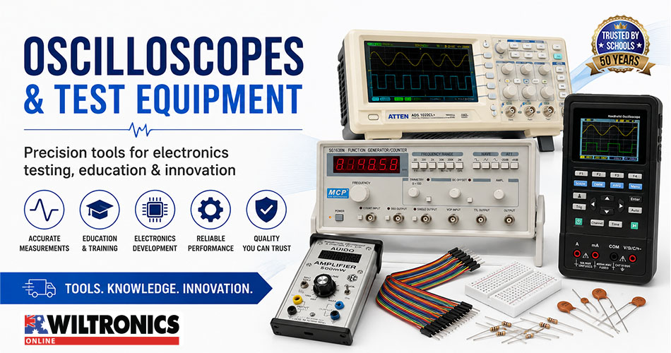
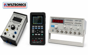
Wiltronics supplies oscilloscopes for schools and technical laboratories, signal and waveform generators and supporting electronic test equipment for physics, electronics, engineering and technical-training programs.
This creates a natural progression from the measurement skills covered in our student multimeter projects for school electronics classes.
Classroom safety: Use supervised, isolated and school-approved low-voltage circuits. Students should not connect oscilloscopes to mains outlets, fixed wiring, switchboards or unknown equipment.
Compare Wiltronics oscilloscope equipment
| Product | Format | Key classroom benefit | Recommended application |
|---|---|---|---|
| 20MHz USB Oscilloscope | Computer-based | Compact footprint and waveform export | Introductory compatible computer workstations |
| 40MHz LCD Handheld Oscilloscope Digital Multimeter | Portable combination instrument | Oscilloscope and multimeter functions in one unit | Technical training and mobile testing |
| 100MHz Two-Channel Digital Oscilloscope | Benchtop | Large display and two-channel analysis | Permanent senior physics and electronics stations |
| Function Generator | Benchtop signal source | Controlled, repeatable waveform output | Frequency, filter and amplifier investigations |
| 60MHz x1/x10 Oscilloscope Probes | Measurement accessory | Switchable attenuation | Replacement probes and additional workstations |
The ideal setup depends on bench space, student experience, portability requirements and whether the class needs to compare two signals simultaneously.
Compare classroom oscilloscope options: Explore the complete Wiltronics oscilloscope and probe range for student workstations, demonstrations and senior electronics laboratories.
1. 20MHz USB Oscilloscope
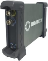
The 20MHz USB Oscilloscope uses a compatible computer to provide the display and controls.
Its compact design takes up less space than a conventional benchtop instrument. The current product listing includes:
- 20MHz bandwidth
- automatic setup
- cursor measurements
- FFT spectrum analysis
- external triggering
- waveform export to Word and Excel files
- two switchable x1/x10 probes
- USB connection
These features make it useful for introductory waveform activities and student reports that require screenshots or exported results.
Best suited to
The USB oscilloscope is a practical choice for:
- compact electronics workstations
- introductory frequency and amplitude measurements
- computer-based practical reports
- audio-frequency experiments
- Arduino signal viewing
- simple filter investigations
Compatibility note
The current listing specifies software support for Windows 2000, XP, Vista, 7 and 8. Schools using newer systems should confirm operating-system compatibility, software installation permissions and network requirements before ordering.
2. 40MHz LCD Handheld Oscilloscope Digital Multimeter

The 40MHz LCD Handheld Oscilloscope Digital Multimeter combines a two-channel oscilloscope and digital multimeter in one portable instrument.
Its oscilloscope has a 40MHz bandwidth and samples at up to 250MSa/s in single-channel mode or 125MSa/s per channel with both channels active. It also includes automatic frequency and amplitude measurement.
The integrated 4000-count multimeter measures voltage, current, resistance, capacitance and diodes. A rechargeable internal battery, protective case, multimeter leads and BNC-to-crocodile-clip cables are included.
Best suited to
The handheld model works well for:
- mobile classroom demonstrations
- technical and vocational training
- workstations with limited bench space
- circuit fault-finding
- comparing multimeter and oscilloscope measurements
- moving between several practical stations
Two instruments in one workstation
Students can begin by using the multimeter to check supply voltage, resistance or continuity.
They can then use the oscilloscope to investigate waveform shape, amplitude, frequency and timing. This makes the handheld model particularly valuable when a program covers both basic circuit testing and more advanced signal analysis.
3. 100MHz Two-Channel Digital Oscilloscope
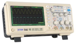
The CRO Oscilloscope 100MHz 2 Channel DSO is the strongest permanent benchtop option in the current Wiltronics range.
It provides:
- two 100MHz channels
- 350MS/s sample rate
- seven-inch colour display
- automatic and cursor measurements
- waveform recording
- digital filtering
- multiple trigger modes
- split-screen waveform and FFT display
- front and rear USB ports
- two included probes
The larger screen and dedicated controls make it suitable for senior students completing repeated signal measurements and two-channel circuit comparisons.
Best suited to
Use the benchtop oscilloscope for:
- permanent senior physics workstations
- electronics laboratories
- input-and-output signal comparisons
- filter and amplifier investigations
- waveform recording
- FFT analysis
- teacher demonstrations
Why two channels matter
Two channels allow students to view an input signal and circuit output at the same time.
They can directly observe:
- attenuation
- amplification
- phase differences
- signal delay
- distortion
- clipping
- filter response
- PWM smoothing
This capability is especially useful when students need to explain what a component or circuit stage does to a signal.
Which oscilloscope suits your classroom?
| Classroom requirement | Recommended product |
|---|---|
| Compact computer-based experiments | 20MHz USB Oscilloscope |
| Portable waveform and multimeter testing | 40MHz Handheld Oscilloscope Digital Multimeter |
| Permanent senior laboratory workstation | 100MHz Two-Channel Digital Oscilloscope |
| Controlled classroom signal generation | Function Generator |
| Sound and waveform demonstrations | IEC Small Audio Amplifier |
A school may use more than one format. A benchtop model can support a permanent demonstration station, while handheld or USB instruments provide additional student workstations.
4. Function Generator
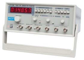
An oscilloscope displays a signal, but a controlled experiment also requires a repeatable signal source.
The Function Generator produces sine, square, triangle, pulse, ramp and 50Hz sine outputs.
The generator section covers frequencies from 0.2Hz to 3MHz. An independent six-digit frequency counter measures from 1Hz to 15MHz. Maximum output is listed as 20V peak to peak into a 1MΩ load or 10V peak to peak into 50Ω.
Use the function generator for
- waveform recognition
- amplitude and frequency measurement
- trigger-setting practice
- RC filter experiments
- amplifier-response testing
- audio-frequency activities
- unknown-waveform assessments
Essential signal source: Pair an oscilloscope with the Function Generator to create repeatable waveform, frequency, filter and amplifier experiments.
Protect student circuits
Begin with the generator output at minimum amplitude.
Check the waveform and voltage on the oscilloscope before connecting the generator to another circuit. Never apply a signal beyond the input rating of the board, component or module being tested.
5. 60MHz x1/x10 Oscilloscope Probes
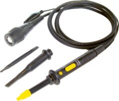
The probe forms part of the complete measurement system.
The 60MHz x1/x10 Oscilloscope Probes provide switchable attenuation for compatible oscilloscopes.
In the x10 position, the listed bandwidth is DC to 60MHz. In the x1 position, it is DC to 15MHz. The x10 setting provides a 10MΩ input resistance when used with an oscilloscope with a 1MΩ input.
These probes suit many classroom audio, PWM and filter activities. However, they will not provide the full bandwidth capability of a 100MHz oscilloscope.
Probe selection affects the accuracy and signal integrity of the complete oscilloscope system. The probe bandwidth, attenuation and input loading should suit the oscilloscope and the signal being measured.
Probe setup checklist
Before each activity, confirm that:
- the probe and cable are undamaged
- x1 or x10 has been deliberately selected
- the oscilloscope channel matches the probe setting
- the ground clip is connected to the approved common point
- the probe is compensated where required
- the probe bandwidth suits the measurement
Five activities using Wiltronics oscilloscope equipment
The following projects show how the featured products can support a progressive waveform-measurement program.
Activity 1: Compare waveform shapes
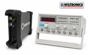
Featured Wiltronics equipment
Student objective
Display and compare sine, square, triangle, pulse and ramp waveforms.
Suggested method
- Reduce the generator output before making connections.
- Select a low-frequency sine wave.
- Adjust the vertical scale until the waveform fits on the display.
- Adjust the time scale until several cycles are visible.
- Set the trigger to stabilise the display.
- Record the waveform shape, frequency and peak-to-peak voltage.
- Repeat using the square, triangle, pulse and ramp outputs.
- Keep frequency and amplitude consistent where practical.
- Compare the captured waveforms.
- Export screenshots for a practical report.
Students can identify which signals contain smooth curves, flat sections, rapid transitions or sloping voltage changes.
The USB oscilloscope is especially useful here because compatible software can export waveforms for use in student reports.
Extension activity
Change one generator control at a time and ask students to identify whether it affects:
- amplitude
- frequency
- period
- pulse width
- symmetry
- waveform shape
Activity 2: Measure amplitude, period and frequency
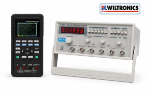
Featured Wiltronics equipment
Student objective
Measure a periodic signal manually, then compare the result with the oscilloscope’s automatic measurements.
Students calculate:
Peak-to-peak voltage = vertical divisions × volts per division
Period = horizontal divisions × time per division
Frequency = 1 ÷ period
For example, if one complete cycle occupies four divisions at 0.5 milliseconds per division:
Period = 4 × 0.5ms = 2ms
Frequency = 1 ÷ 0.002s = 500Hz
Suggested results table
| Signal | Volts per division | Vertical divisions | Peak-to-peak voltage | Time per division | Cycle divisions | Period | Frequency |
|---|---|---|---|---|---|---|---|
| A | |||||||
| B | |||||||
| C |
The handheld model’s automatic frequency and amplitude functions allow students to check their manual calculations. Its integrated multimeter can also measure the same source, helping students compare a numerical meter reading with a complete waveform display.
Activity 3: Compare an RC filter input and output
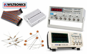
Featured Wiltronics equipment
- 100MHz Two-Channel Digital Oscilloscope
- Function Generator
- breadboards and prototyping equipment
- breadboard jumper wires
- resistors and capacitors
Example low-pass filter
Use:
- 10kΩ resistor
- 10nF capacitor
- 1V peak-to-peak sine-wave input
- output measured across the capacitor
The approximate cutoff frequency is:
fc = 1 ÷ (2πRC)
For these component values:
fc ≈ 1.59kHz
Suggested test frequencies are:
- 160Hz: well below the cutoff
- 1.6kHz: near the cutoff
- 16kHz: well above the cutoff
Circuit layout
Function generator output
          |
        10kΩ
          |
          +-------- Output to Channel 2
          |
        10nF
          |
Circuit common
Connect Channel 1 to the circuit input and Channel 2 to the output across the capacitor. Connect both probe ground clips to the approved circuit common.
Student investigation
At each frequency, students record:
- input peak-to-peak voltage
- output peak-to-peak voltage
- output-to-input amplitude ratio
- visible timing or phase difference
The two-channel benchtop oscilloscope is particularly suited to this project because it can display both waveforms simultaneously and includes automatic, cursor and recording functions.
Building senior electronics workstations? Contact the Wiltronics team to discuss oscilloscopes, function generators, probes and classroom quantities.
Activity 4: View audio waveforms
Featured Wiltronics equipment
The IEC Small Audio Amplifier has an integrated speaker and https://www.wiltronics.com.au/product/82902/oscilloscope-digital-multimeter/accepts input through a 3.5mm socket or banana-plug connection. It also provides 4mm output sockets for connecting an oscilloscope and viewing the signal.
The amplifier can operate from a 9V battery or a suitable 12V AC or DC supply.
Student objective
Investigate how pitch and signal level affect an electrical audio waveform.
Suggested method
- Begin with the source and amplifier levels low.
- Connect the oscilloscope to the amplifier’s approved output.
- Display a steady audio-frequency sine wave.
- Measure its period and frequency.
- Increase the frequency and observe the shorter period.
- Change the signal amplitude.
- Observe the change in waveform height.
- Increase the input cautiously and look for clipping.
- Compare simple tones with speech or music.
- Record screenshots or waveform sketches.
Concepts to explore
Pitch and frequency: A higher-pitched tone produces more cycles in the same time interval.
Signal level and amplitude: A larger electrical signal appears taller on the display.
Pure and complex signals: A sine wave has a simple repeating shape, while speech and music contain several frequency components.
Clipping: Driving an amplifier beyond its available output range can flatten the waveform peaks and produce audible distortion.
Teachers can also explore Arduino-compatible audio modules when combining audio, coding and signal measurement.
Three Wiltronics workstation configurations
Introductory computer-based station
Combine:
- 20MHz USB Oscilloscope
- Function Generator
- solderless breadboard
- jumper wires
- resistor and capacitor assortment
This configuration suits waveform recognition, frequency measurement, screenshots and introductory filter experiments.
Confirm computer compatibility before purchasing the USB model.
Portable technical-training station
Combine:
- 40MHz Handheld Oscilloscope Digital Multimeter
- compact breadboard circuits
- multimeter test leads and accessories
- ARD2 Arduino-Compatible Kit
This provides multimeter and oscilloscope functions in one portable instrument.
Senior physics and electronics station
Combine:
- 100MHz Two-Channel Digital Oscilloscope
- Function Generator
- suitable probes
- IEC Small Audio Amplifier
- laboratory benchtop power supply
- breadboards and component assortments
This workstation supports two-channel filter measurements, audio experiments, amplifiers, PWM and advanced waveform analysis.
Oscilloscope connection safety
On many conventional oscilloscopes, the probe reference is connected to protective earth through the instrument.
Connecting the reference clip to an unsuitable circuit point can create an unintended short circuit. Do not defeat the oscilloscope’s protective grounding system to make a floating measurement.
For classroom work:
- use approved isolated low-voltage sources
- inspect probes and cables before use
- identify circuit common before connecting a probe
- connect channel grounds to the same approved common point
- switch off circuits before moving clips
- follow the instrument manual
- have unfamiliar setups checked before power is applied
Frequently asked questions
Which Wiltronics oscilloscope is best for schools?
The USB model suits compact compatible computer workstations.
The handheld model is useful when portability and integrated multimeter functions are priorities. The 100MHz benchtop model is the strongest choice for permanent senior physics and electronics laboratories requiring a larger display and two-channel analysis.
Does an oscilloscope replace a multimeter?
No. The instruments complement each other.
A multimeter is usually faster for resistance, continuity and basic voltage checks. An oscilloscope is more useful when waveform shape, timing, frequency or rapid voltage changes matter.
Does every workstation need a function generator?
A function generator is valuable when students need controlled and repeatable waveforms.
One unit can support a demonstration station, while one per student group provides greater independence during waveform, filter and amplifier investigations.
Can the 60MHz probes be used with the 100MHz oscilloscope?
They can be used for signals within their specifications, but they limit the bandwidth of the complete measurement system.
The featured probes provide up to 60MHz bandwidth in x10 mode, so they cannot deliver the full 100MHz bandwidth of the benchtop oscilloscope.
Can students connect an oscilloscope to an Arduino?
Yes, when working with an approved low-voltage Arduino circuit.
Connect the probe reference to Arduino ground and the probe tip to the signal pin. Confirm the probe attenuation and channel settings before recording measurements.
Which product is best for sound experiments?
The IEC Small Audio Amplifier is designed for student use and includes an integrated speaker and dedicated 4mm outputs for oscilloscope connection. It can be paired with the Function Generator or another suitable audio source.
Build a Wiltronics waveform-measurement workstation
Wiltronics offers oscilloscope options for compact computer stations, portable technical training and permanent senior electronics laboratories.
Pairing the selected instrument with a function generator, suitable probes, breadboards, components and project equipment gives students a complete pathway from recognising waveform shapes to analysing filters, audio signals and PWM.
Explore:
- oscilloscopes and probes
- signal and waveform generators
- electronic test equipment
- physics equipment for schools
- Arduino and Arduino-compatible products
For help comparing oscilloscope models, matching probes or planning classroom quantities, contact Wiltronics.
© Electrotech Brands Pty Ltd 2026
Write a Comment
You must be logged in to post a comment.